Supercharge Your Innovation With Domain-Expert AI Agents!

High Voltage Clamp Current Transformer

A technology of current transformers and clamps, which is applied in the direction of inductors, voltage/current isolation, transformers, etc., and can solve problems such as complex live working methods and equipment

Active Publication Date: 2015-09-02
珠海市华优电气技术有限公司
View PDF4 Cites 0 Cited by
  • Summary
  • Abstract
  • Description
  • Claims
  • Application Information

AI Technical Summary

Problems solved by technology

Install or remove the high-voltage clamp-on current transformer on the high-voltage cable, which usually requires power failure or more complex live working methods and equipment

Method used


Image

  • High Voltage Clamp Current Transformer
  • High Voltage Clamp Current Transformer
  • High Voltage Clamp Current Transformer

Examples


Embodiment Construction

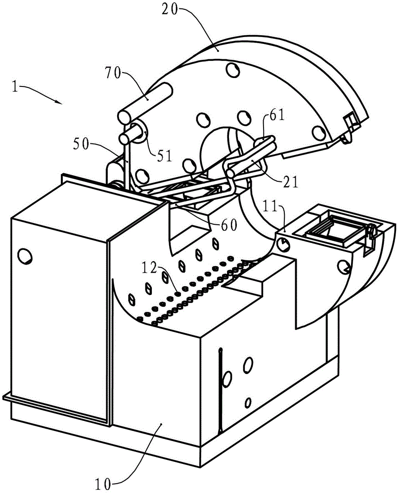
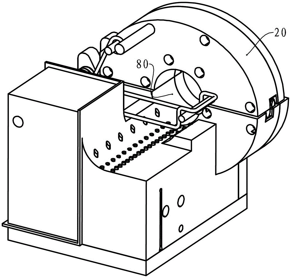
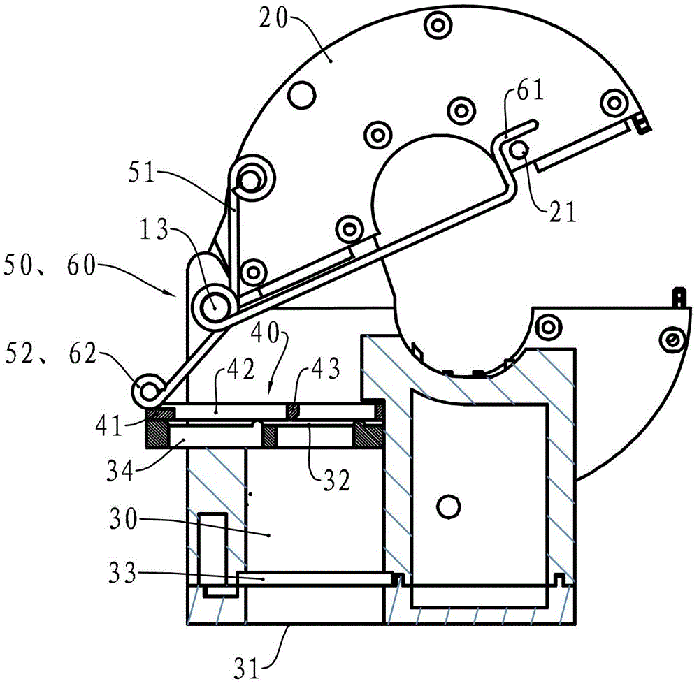
[0020] see figure 1 , figure 1 It shows a perspective view in which the movable clamp arm 20 of a high-voltage clamp current transformer 1 is in an open state, and the circuit part of the current transformer is housed in its housing 10, and a wireless transmitting circuit is also housed, which is used to place the The obtained current parameters are transmitted to ground. The movable caliper arm 20 is mounted on the housing 10 through a hinge. Torsion spring 50 is installed on the hinge, and its one end figure 1 Not visible, the other end 51 is fixed on the caliper arm 20 . Pressing cable torsion spring 60 is also installed on the hinge, and one end of it figure 1 Not visible in the figure, the other end 61 rides on the spring rod 21 protruding from the movable pliers arm 20 . A stop rod 70 is also provided on the movable caliper arm 20 . A fixed clamp arm 11 is formed on the housing 10, and anti-slip teeth 12 are provided on the surface area of ​​the jaw, that is, the c...


PUM


Abstract

The invention relates to a high-voltage split-core type current transformer, which comprises a shell, a movable clamp arm, a seat hole, a sliding plate, a torsion spring and a stop bar, wherein at least the circuit of the current transformer is installed in the shell; the movable clamp arm is connected onto the shell through a hinge, and a line passing channel is formed between the movable clamp arm and a fixed clamp arm on the shell when the movable clamp arm turns to a closed state; the seat hole is provided with a circular entrance and a circular exit on the shell, the axis of the seat hole is vertical to the axis of the hinge, and a circumferential-surrounded groove is arranged in the inner wall near the entrance; the sliding plate is installed on the shell in a plane vertical to the axis of the seat hole and is provided with a lapping part, a release port and a triggering part; the torsion spring is installed on the shell, and the restoring force of the torsion spring forces the movable clamp arm to turn to the closed state; when the triggering part is positioned in the exit, one end of the torsion spring can be butted against the lapping part; when the triggering part is stressed to slide to the outer part of the exit, one end of the torsion spring is separated from the lapping part and is in a free state; the stop bar extends out from the movable clamp arm; when the movable clamp arm turns to a fully open state, the stop bar is positioned at one side of the axis of the seat hole; and when the movable clamp arm turns to a fully closed state, the stop bar is positioned at the other side of the axis of the seat hole. The high-voltage split-core type current transformer can be installed on or taken down from a high voltage cable through a high-voltage insulation operating bar.

Description

technical field [0001] The invention relates to a high-voltage power measuring tool, in particular, a high-voltage clamp current transformer for measuring the current of a high-voltage cable. Background technique [0002] An invention patent with the authorized announcement number CN101266263B discloses a power metering supervision system and a supervision method. The system includes an electric energy meter and a metering supervisory host, which respectively calculate the electric energy on the first side of the transformer and the electric energy on the second side. The metering supervisory host stores a threshold value and calculates the relative difference of the electric energy data on both sides of the transformer. When the relative difference is greater than An alarm message is generated when the threshold is reached, and the communication module can send the alarm message. The method includes installing an electric energy meter and a metering supervisory host on the...

Claims


Application Information

Patent Timeline
Patent Type & Authority Patents(China)
IPC IPC(8): H01F38/30G01R15/18
Inventor 徐国华
Owner 珠海市华优电气技术有限公司
Features
  • R&D
  • Intellectual Property
  • Life Sciences
  • Materials
  • Tech Scout
  • Unparalleled Data Quality
  • Higher Quality Content
  • 60% Fewer Hallucinations
Learn More