Shed-forming device for a weaving machine

A shed and loom technology, applied in the field of producing such a shed forming device, can solve problems such as changing the movement route, and achieve the effect of easy setting or adjustment

Active Publication Date: 2013-07-24
PICANOL NV
View PDF8 Cites 3 Cited by
  • Summary
  • Abstract
  • Description
  • Claims
  • Application Information

AI Technical Summary

Problems solved by technology

However, it is usually not possible to change the line of motion without dismantling the drive unit

Method used


Image

  • Shed-forming device for a weaving machine
  • Shed-forming device for a weaving machine
  • Shed-forming device for a weaving machine

Examples


Embodiment Construction

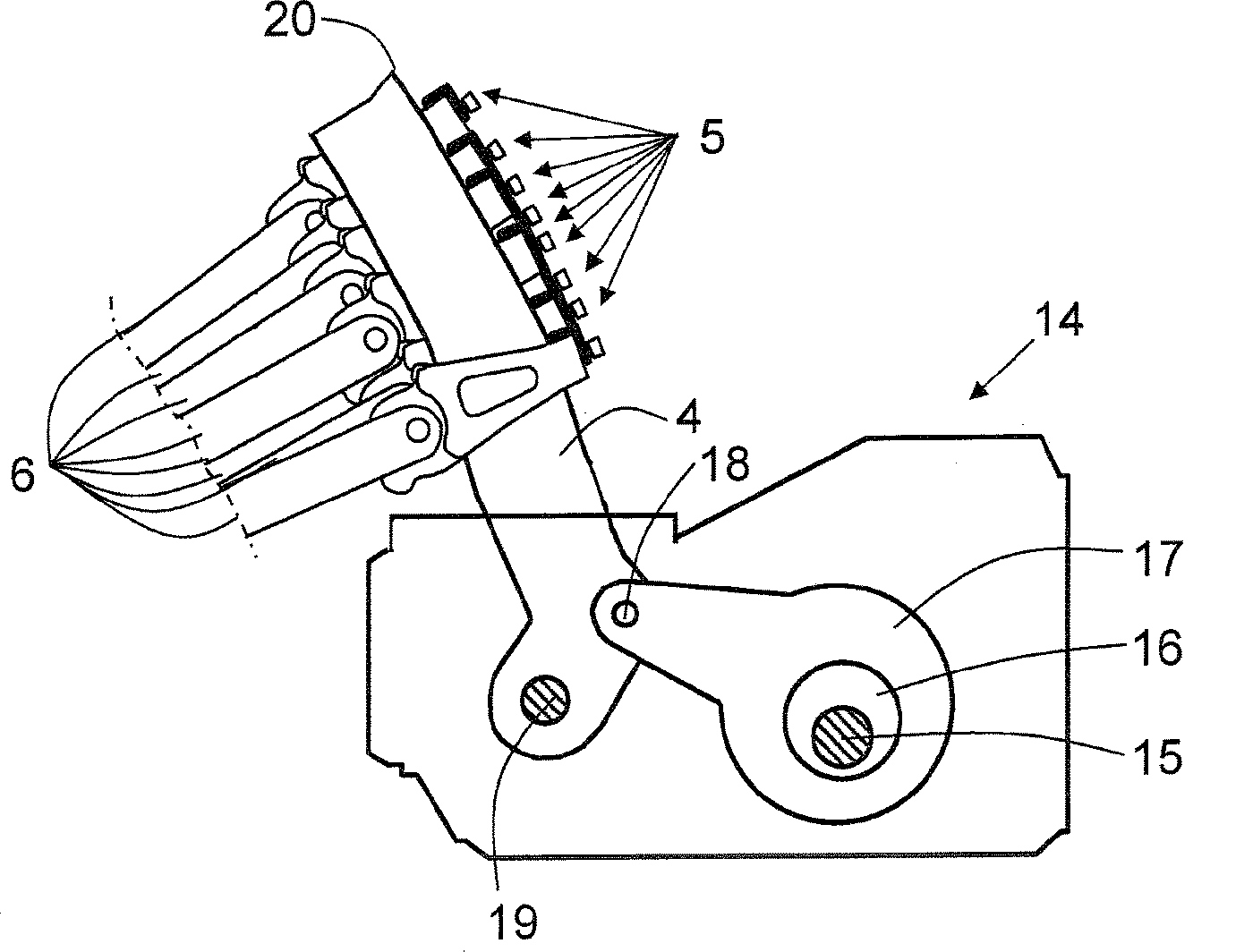
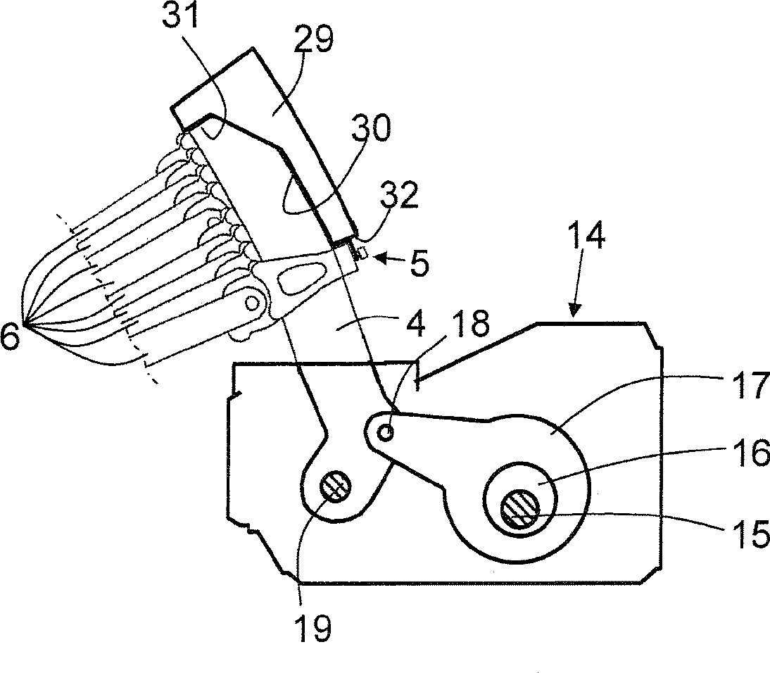
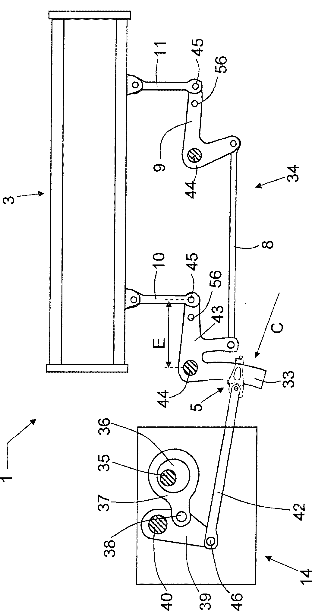
[0047] FIG. 1 schematically shows a perspective view of an embodiment of a shedding device 1 with a plurality of transmissions 2 each connected to a heald frame 3 . In general, weaving is carried out with at least two different heald frames 3 , each driven via an associated transmission 2 . For clarity of illustration, only two heald frames 3 are shown. The shedding device 1 also comprises a different drive rod 4 connected to the bar 6 of the transmission mechanism 2 via a settable connection 5 . The transmission mechanism 2 also includes a first hinge rod 7 , a horizontal rod 8 , a second hinge rod 9 and vertical rods 10 and 11 . The transmission mechanism is used to convert the reciprocating motion of the coupled driving rod 4 into the up and down motion of the heald frame 3 . In this case, the heald frame 3 can move in guides 12 and 13 of the loom (not shown). Furthermore, a drive device 14 for driving the drive rod 4 is shown. With a plurality of heald frames 3 a shed ...


PUM


Abstract

Shed-forming device comprising a number of drive levers (4, 33) and a number of transmission mechanisms (2, 34), wherein each transmission mechanism (2, 34) can drive a heald frame (3) and can be driven by a driving device (14) via a drive lever (4, 33), wherein the transmission mechanism (2, 34) and the drive lever (4, 33) are coupled in a specific coupling position by means of a connection (5), and wherein at least one indication (22, 23, 27, 28, 46) for a reference coupling position is provided on at least one drive lever (4, 33). Method for producing and method for setting a shed-forming device (1) for a weaving machine.

Description

technical field [0001] The invention relates to a shedding device for a weaving machine comprising a plurality of drive rods and a plurality of transmissions, wherein each transmission can drive a heald frame and can be driven by the drive device via the drive rod. The invention also relates to a method for producing such a shedding device and a method of using such a shedding device. Background technique [0002] In a weaving machine, a shedding device is used to form warp thread planes between which sheds are formed to allow weft threads to be introduced into the sheds. Known shedding devices generally drive at least two heald frames and comprise a transmission for each heald frame to move the heald frames up and down, and a drive rod driven by a drive to drive the transmission for the heald frames . The transmission mechanism is usually driven by a drive device, such as a dobby, a cam box, an eccentric mechanism or any other drive device. [0003] Such a drive arrangem...

Claims


Application Information

Patent Timeline
Patent Type & Authority Applications(China)
IPC IPC(8): D03C1/14D03C5/00
CPCD03C1/144D03C5/00D03C1/14
Inventor D.萨姆佩尔斯K.勒尔施特拉特
Owner PICANOL NV
Why Eureka
Try Eureka