
Gas pump with reduced noise generation

A technology of air pumps, pump housings, applied in the direction of pumps, pump elements, parts of pumping devices for elastic fluids, capable of solving problems such as discomfort

Inactive Publication Date: 2013-07-24
CONTINENTAL AUTOMOTIVE GMBH
View PDF5 Cites 0 Cited by
  • Summary
  • Abstract
  • Description
  • Claims
  • Application Information

AI Technical Summary

Problems solved by technology

As in most pumps, the medium output by the vane pump is affected by the pulsation and causes noise, which can make people in the motor vehicle area uncomfortable

Method used


Image

  • Gas pump with reduced noise generation
  • Gas pump with reduced noise generation
  • Gas pump with reduced noise generation

Examples


Embodiment Construction

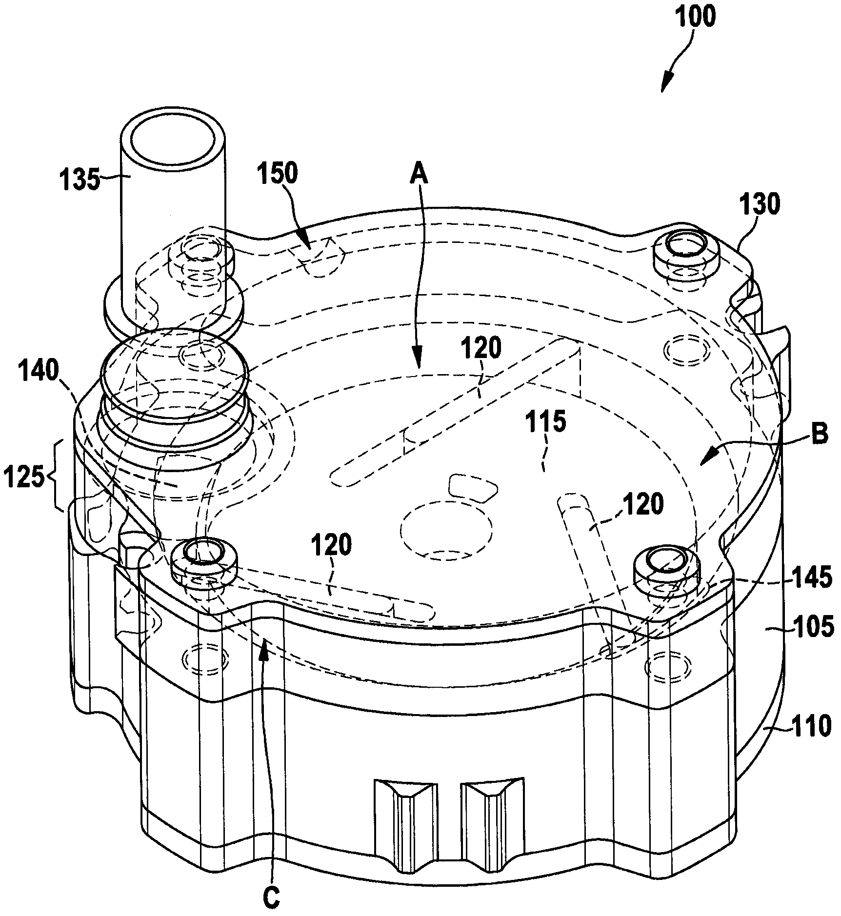
[0017] figure 1 A perspective view of the air pump 100 is shown. The air pump 100 comprises a pump housing 105 which is closed downwards by a pump base 110 . A pump rotor 115 is arranged in the pump housing, which is rotatable about a vertical axis. For this purpose, the pump rotor 115 is driven by means of a shaft (not shown) by an electric motor arranged below the pump floor 110 .

[0018] The pump rotor includes three slots extending at an angle from a circumference around the axis of rotation of the pump rotor to the outer edge of the pump rotor 115 . A sliding element 120 is accommodated in each of the grooves, which is held in the inner circumference of the pump housing 105 by centrifugal force and / or spring elements. The inside of the pump housing 105 is a cylindrical shell surface around a central axis that is offset parallel to the axis of rotation of the pump rotor 115 . The pump units (Pumpenzelle) A to C therefore have different volumes, which are related to th...


PUM


Abstract

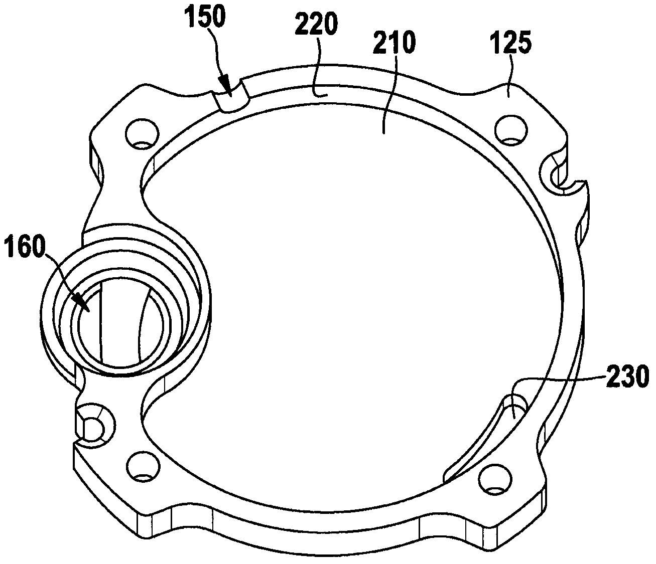
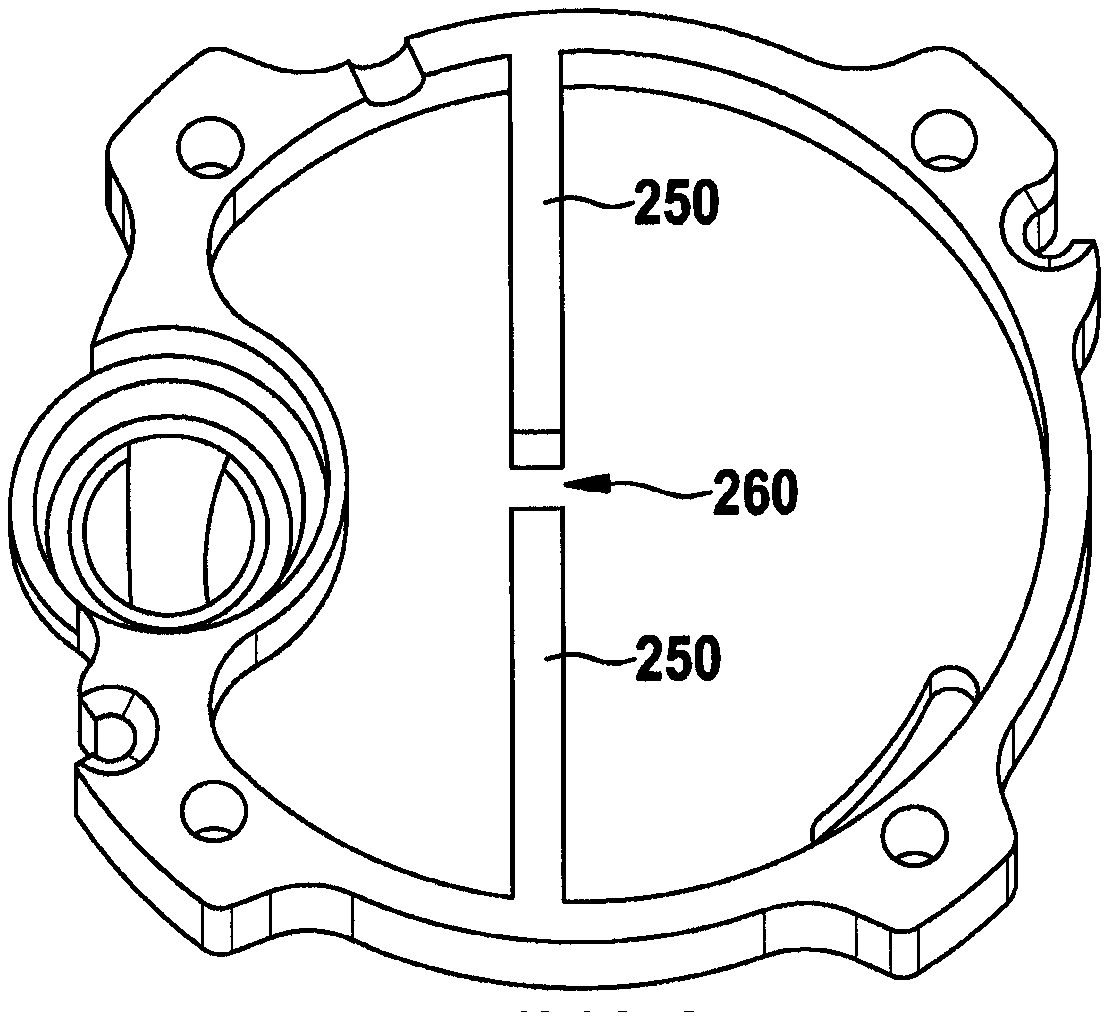
A gas pump comprises a pump rotor for conveying a gaseous medium, a pump housing in which the pump rotor is rotatably accommodated, a delimiting element which closes off the pump housing in the axial direction, and a closure element which, together with the delimiting element, forms a sound absorber. The delimiting element has an opening for the passage of medium between the pump housing and the sound absorber, and has a web which extends in the axial direction and which runs around the opening in the radial direction, wherein the closure element bears against the web in the axial direction.

Description

Background technique [0001] For conveying gaseous media, various pumps are used, for example, in the area of ​​motor vehicles. To generate the low pressure, which is necessary, for example, in low-pressure controlled brake boosters, vane pumps are usually used. As in most pumps, the pulsation of the medium delivered by the vane pump causes noise which can be uncomfortable for persons in the motor vehicle area. [0002] DE 199 36 644 A1 proposes the design of an air pump with an integrated silencer, wherein the silencer is a cylindrical cavity into which the medium flowing out of the pump chamber flows. The cap member houses the pump chamber and encloses a cavity between the pump chamber and the inner boundary of the cap. Contents of the invention [0003] The object of the present invention is to provide a pump with an integrated silencer that is easy to manufacture. [0004] The problem of the invention is solved by a pump having the features of claim 1 . The dependent ...

Claims


Application Information

Patent Timeline
IPC IPC(8): F01C21/10F04C29/12F04C29/06F04C18/344
CPCF04C29/068F04C29/061F04C29/12F04C18/3441F01C21/10F04C2220/10
Inventor A·约翰宁H·克吕格
Owner CONTINENTAL AUTOMOTIVE GMBH
Learn More