Bag sleeving device

A bagging device and bagging technology, applied in the direction of packaging, etc., can solve problems such as overturning and bagging cannot be carried out

Inactive Publication Date: 2013-07-31
无锡市开维物流装备有限责任公司
View PDF5 Cites 13 Cited by
  • Summary
  • Abstract
  • Description
  • Claims
  • Application Information

AI Technical Summary

Problems solved by technology

When the bag is too soft, the upper side of the bag of the vacuum suction cup will fall off, making the bagging impossible

Method used


Image

  • Bag sleeving device
  • Bag sleeving device
  • Bag sleeving device

Examples


Embodiment Construction

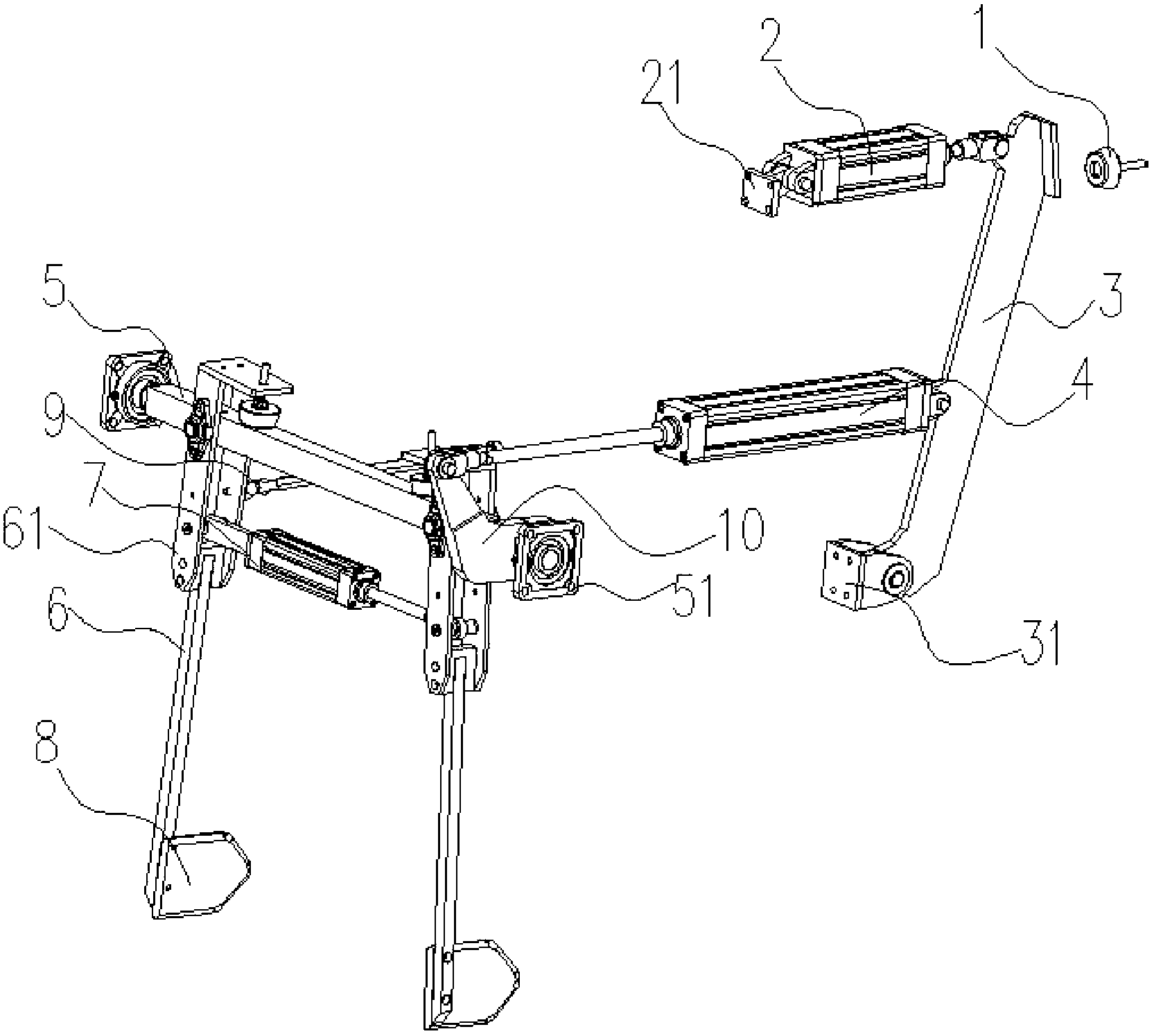
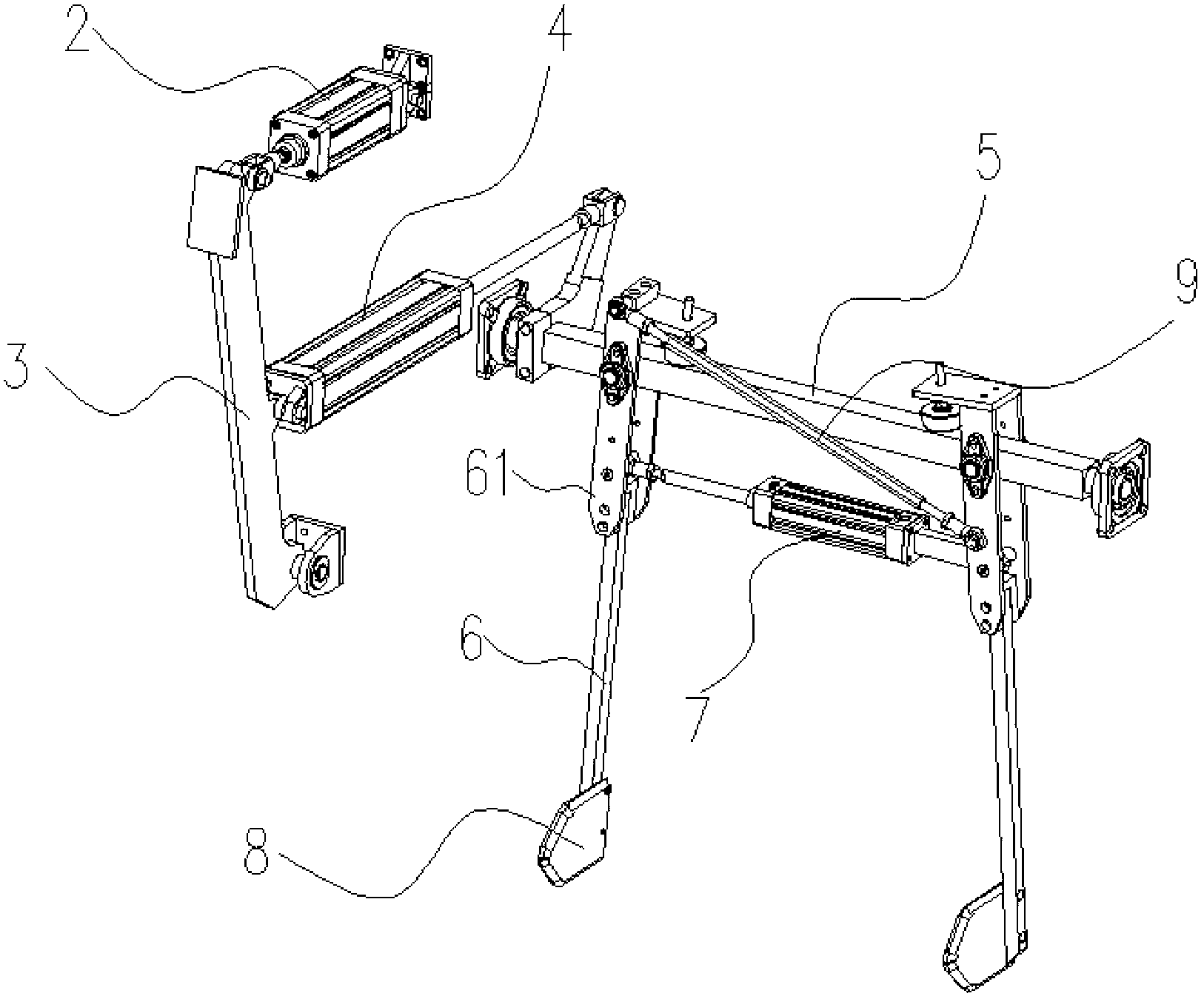
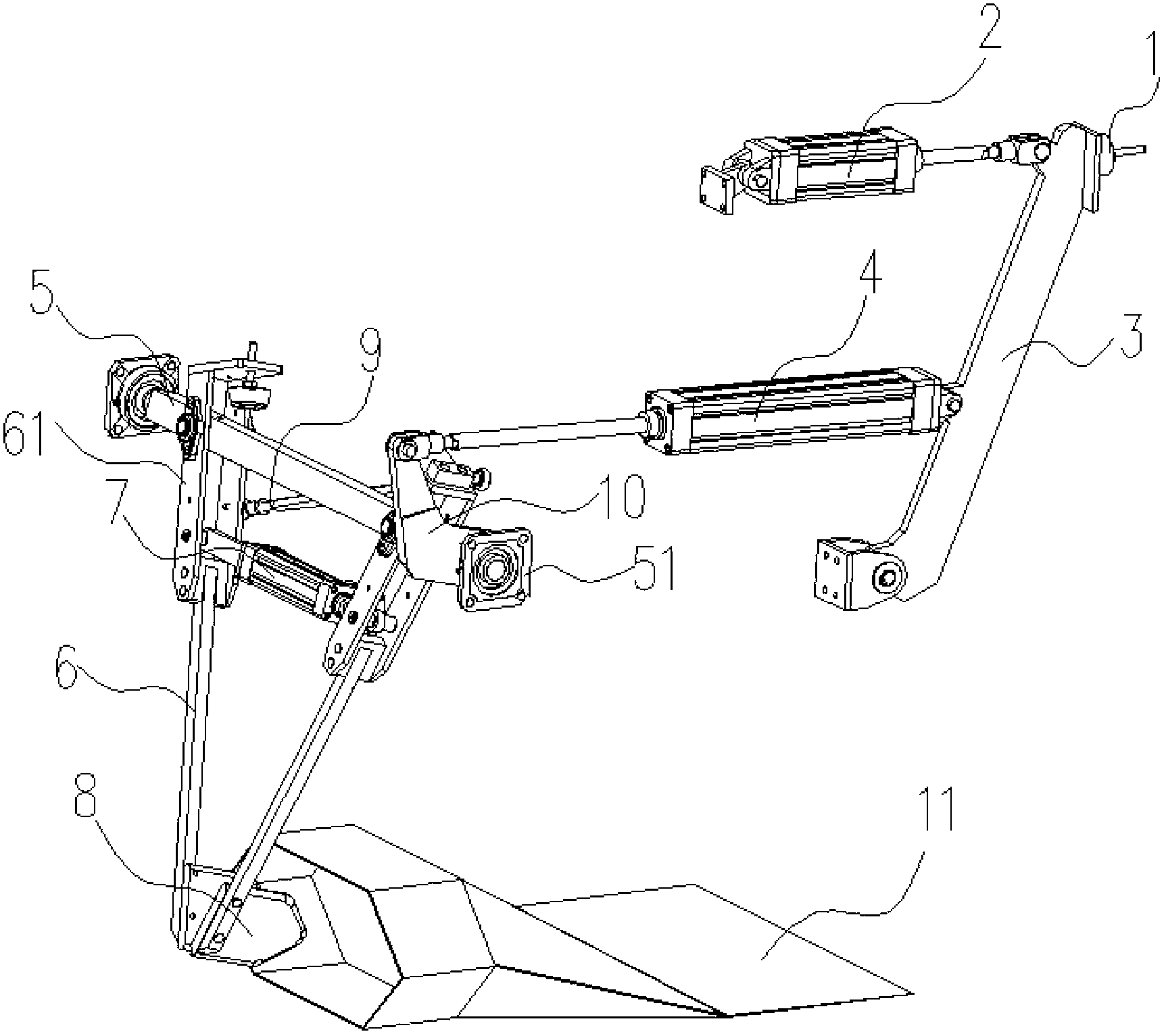
[0018] Such as Figure 1-2 As shown, the present invention provides a bagging device, including a rotating shaft 5, a swing arm 6 and a power system. The rotating shaft 5 is arranged horizontally, and the two swing arms 6 are arranged vertically, and the two swing arms 6 are installed on the rotating shaft 5 correspondingly. The two swing arms 6 are connected to the rotating shaft 5, and the swing arms 6 are connected to the rotating shaft 5 through a connector 61, and the connector 61 is connected to the rotating shaft 5 through screws to ensure that the swing arm 6 can swing along the axial direction of the rotating shaft 5. The power system drives the rotation of the rotating shaft 5 and the swing of the swing arm 6 . The lower end of the swing arm 6 is provided with a support plate 8 . The power system includes a main cylinder 4 , an auxiliary cylinder 2 and a bagging cylinder 7 , one end of the main cylinder 4 is connected with the rotating shaft 5 through a pivot arm 1...


PUM


Abstract

The invention discloses a bag sleeving device which comprises a rotary shaft, swing arms and a power system, wherein the two swing arms are correspondingly mounted on the rotary shaft; supporting plates are arranged at the lower ends of swing arms; the two swing arms are fixedly connected with the rotary shaft; and the power system drives the rotary shaft to rotate, drives the swing arms to swing, and can swing axially along the rotary shaft. The operation process of the bag sleeving device comprises the following steps: preparing bag taking: the mouth of a bag is opened, a main air cylinder and an auxiliary air cylinder expand, a bag sleeving air cylinder contracts, and the two supporting plates are closed; taking the bag: the auxiliary air cylinder contracts, the two supporting plates are sent into the mouth of the bag; sleeving the bag: the bag sleeving air cylinder expands, and the two supporting plates take the bag from a bag opening device; sleeving the bag: the main air cylinder contracts, the opened bag is sent to a bag dragging device by the swing arms; returning the supporting plates: the main air cylinder expands, and the supporting plates are sent back by the swing arms; and waiting for bag taking: the bag sleeving air cylinder contracts, the two supporting plates are closed, and a bag sleeving device is in the state of preparing bag taking.

Description

technical field [0001] The invention belongs to the field of packaging machinery, and more specifically relates to a bagging device. Background technique [0002] In the existing bagging mechanism, the bag is sent from the original position to the bag clamping device. Due to the use of vacuum grabbing, the vacuum state of the bag is always maintained during this process, and the bag is moving, so a vacuum will occur. Leakage conditions make the bagging unreliable. When the bag is too soft, the upper side of the bag of the vacuum suction cup will fall off, making it impossible to carry out bagging. Contents of the invention [0003] The invention provides a bagging device, which is used in front of the bagging process to stretch the bag, so that the bag is easier to be bagged. [0004] According to one aspect of the present invention, a bagging device is provided, including a rotating shaft, a swing arm and a power system, the two swing arms are correspondingly installed ...

Claims


Application Information

Patent Timeline
Patent Type & Authority Applications(China)
IPC IPC(8): B65B43/46B65B43/30
Inventor 孔祥胜濮阳人平魏小超席亚珠唐升裕林伟
Owner 无锡市开维物流装备有限责任公司
Why Eureka
Try Eureka