Feeding device for metal band sawing machine

A technology of metal strip and sawing machine, which is applied in the direction of sawing machine, metal sawing equipment, metal processing equipment, etc. It can solve the problems of inability to cut bar material, reprocessing and inclination of the end of bar material, etc., and achieve the effect of increasing cutting diversity

Inactive Publication Date: 2021-01-22
安徽运杰机械设备制造有限公司
View PDF1 Cites 0 Cited by
  • Summary
  • Abstract
  • Description
  • Claims
  • Application Information

AI Technical Summary

Problems solved by technology

[0006] Under the limitation of the material structure of the existing metal band sawing machine, the cut surface of the bar can only be perpendicular to its axis, and it is impossible to cut the cut surface that is not perpendicular to its axis on the bar, such as when multiple sections of the bar are required to be spliced ​​to form a polygon. When framed, the cut surface of the bar is not perpendicular to its axis, causing the end of the bar produced by the prior art to be reprocessed to form an inclined cut surface

Method used


Image

  • Feeding device for metal band sawing machine
  • Feeding device for metal band sawing machine
  • Feeding device for metal band sawing machine

Examples


Embodiment Construction

[0037] The present invention will be described in further detail below in conjunction with the accompanying drawings.

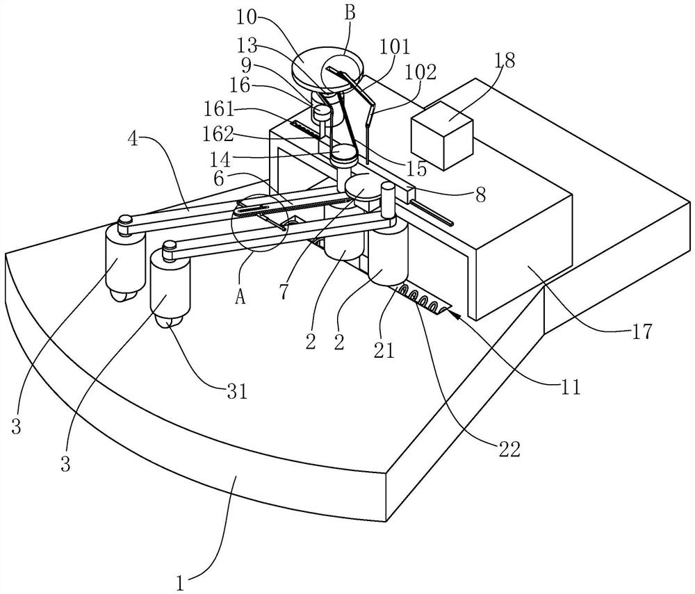
[0038] Such as figure 1 As shown, a feeding device for a metal band sawing machine includes a base 1, a pair of driving rollers 2 and a pair of guide rollers 3 are arranged on the base 1, and the axes of the driving roller 2 and the guide rollers 3 are all extended along the vertical direction , and the driving roller 2 and the guide roller 3 both rotate around their axes, wherein the lower ends between the driving rollers 2 move relative or opposite each other in the horizontal direction, and the two guide rollers 3 rotate around the axis of one of the driving rollers 2 respectively and are installed on the base 1 , and the distance between the axes of the guide rollers 3 is always equal to the distance between the axes of the driving rollers 2;

[0039] Insert the bar between the driving roller 2 and the guide roller 3, and then drive the driving roller 2 ...


PUM


Abstract

The invention relates to a feeding device for a metal band sawing machine. The feeding device comprises a base, wherein a pair of driving rollers and a pair of guide rollers are arranged on the base;the axes of the driving rollers and the axes of the guide rollers extend in the vertical direction, and the driving rollers and the guide rollers rotate around the respective axes; the lower ends of the driving rollers move oppositely or reversely in the horizontal direction; the two guide rollers are rotationally arranged on the base around the axis of one driving roller respectively; and the distance between the axes of the guide rollers is always equal to the distance between the axes of the driving rollers. The driving rollers and the guide rollers are used for controlling rotation and feeding of bars, and thus machining of the bars at different cutting angles is achieved.

Description

technical field [0001] The invention relates to the technical field of metal band sawing machines, in particular to a feeding device for metal band sawing machines. Background technique [0002] A metal band saw is a machine tool used to cut metal. [0003] The patent with the existing notification number CN208276289U discloses a clamping mechanism for metal band sawing machines, including a workbench, on which a pair of bases are arranged, and the bases move relative or opposite to each other along the length direction of the workbench. A pair of clamping blocks are provided for relative or opposite movement; [0004] Before cutting the metal strip, the metal strip is placed between the clamping blocks, and by moving the base to both sides of the length direction of the metal strip, and pressing and fixing the metal strip through the clamping block, the metal strip is realized. Material fixation. [0005] There are following defects in the above-mentioned prior art schem...

Claims


Application Information

Patent Timeline
Patent Type & Authority Applications(China)
IPC IPC(8): B23D55/04
CPCB23D55/04B23D55/043
Inventor 蒋友河
Owner 安徽运杰机械设备制造有限公司
Why Eureka
Try Eureka