Image forming apparatus

An image and equipment technology, applied in the field of image forming equipment, can solve problems such as jamming and sheet contact

Active Publication Date: 2013-07-31
BROTHER KOGYO KK
View PDF11 Cites 2 Cited by
  • Summary
  • Abstract
  • Description
  • Claims
  • Application Information

AI Technical Summary

Problems solved by technology

[0003] However, in such an image forming apparatus, since the end portion of the tray cover is located above the discharge roller nip, if the user accidentally gives a print instruction while the tray cover is in the cover position, the output from the discharge roller nip Ejected sheets may touch the lower surface of the tray cover and jam

Method used


Image

  • Image forming apparatus
  • Image forming apparatus
  • Image forming apparatus

Examples


Embodiment Construction

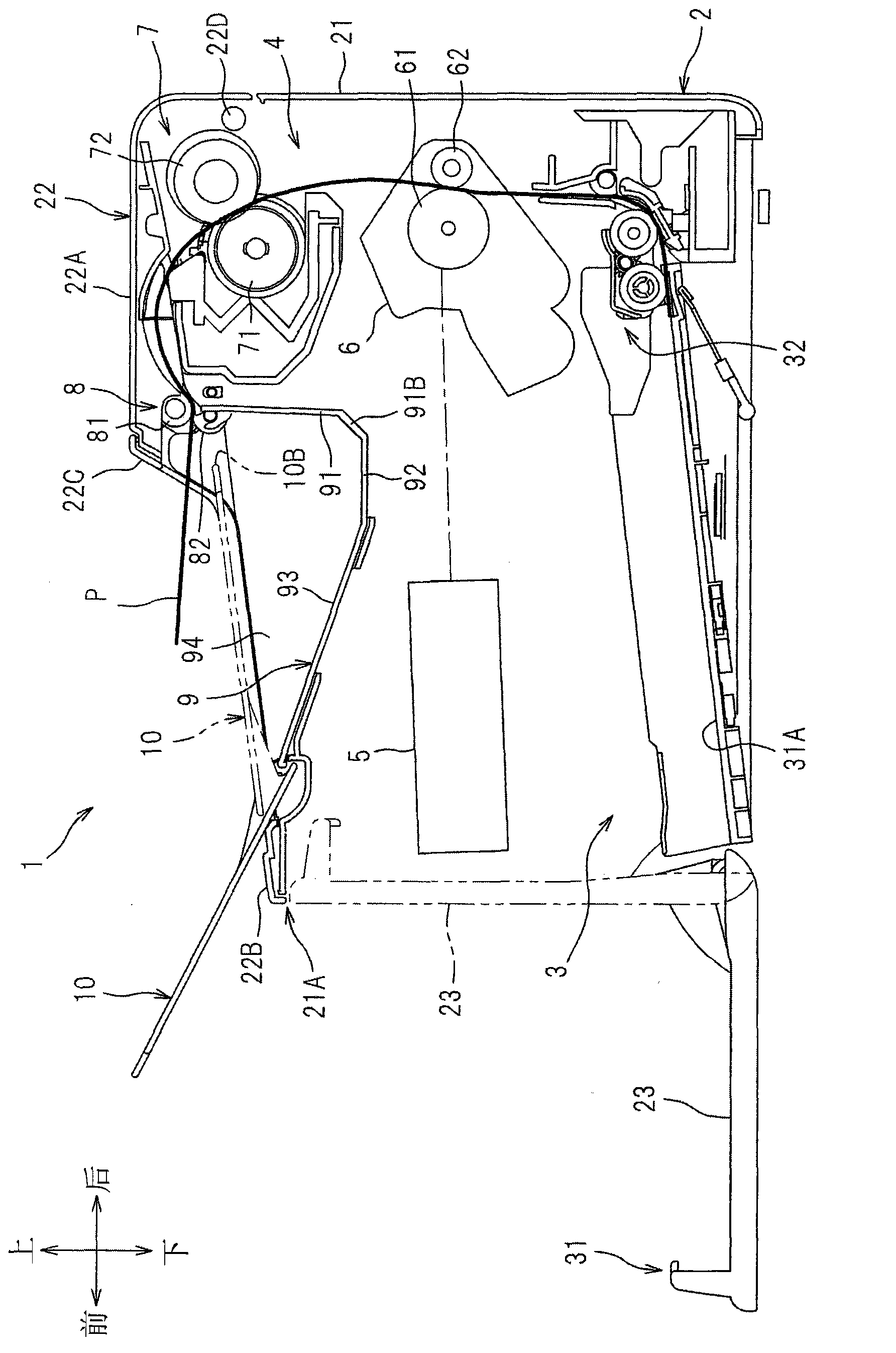
[0016] An exemplary embodiment will be described in detail with reference to the accompanying drawings. Hereinafter, a general structure of a laser printer as an example of an image forming apparatus will be described, and then features of the present invention will be described in detail.

[0017] Hereinafter, the direction or side of the laser printer will be based on the orientation in which the laser printer is placed to be used. In other words, in figure 1 In , the left side is called the front or front side, the right side is called the back or rear side, the upper side is called the upper side or the upper side, and the lower side is called the lower side or the lower side. The up and down direction may be referred to as a vertical direction.

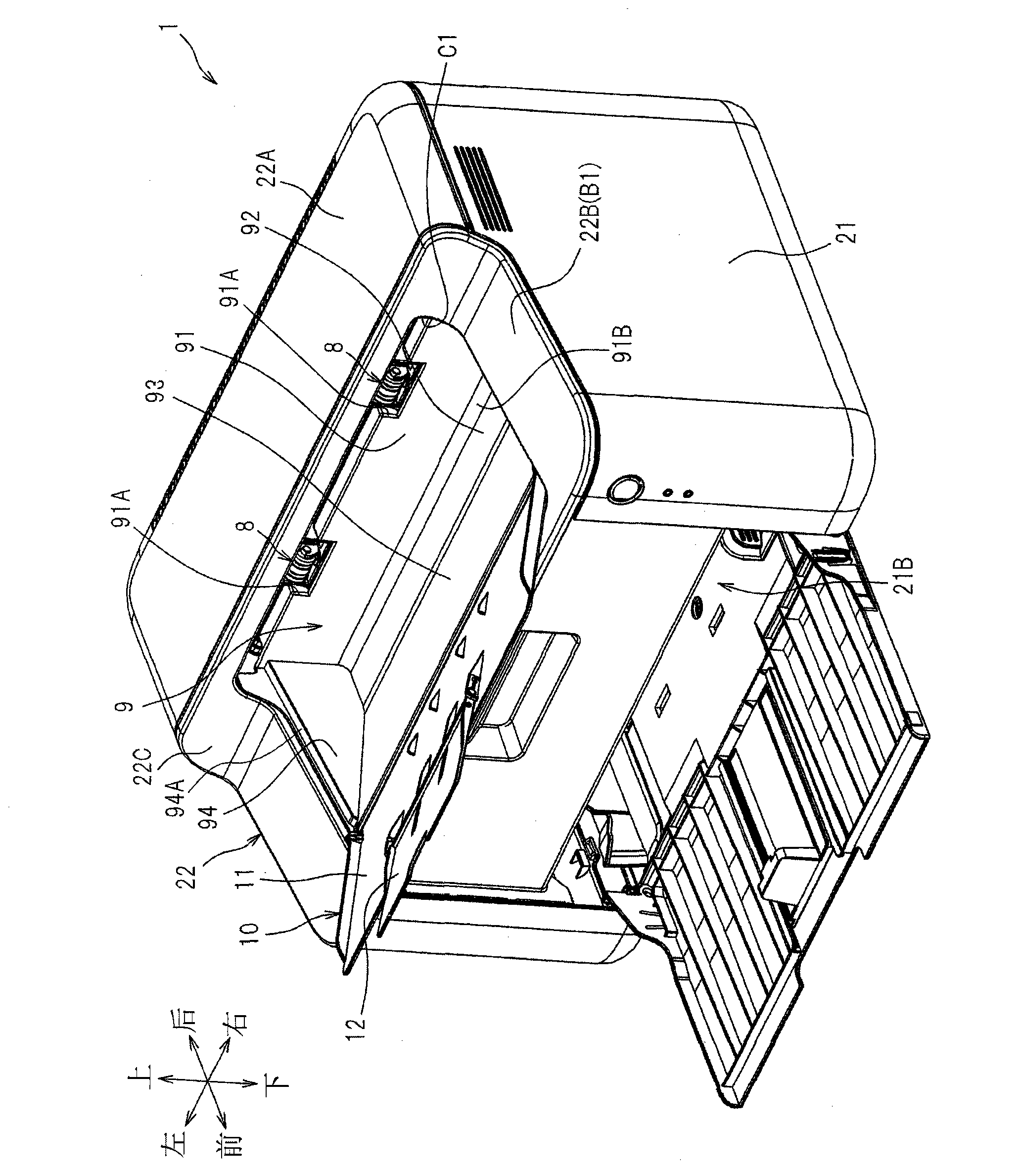
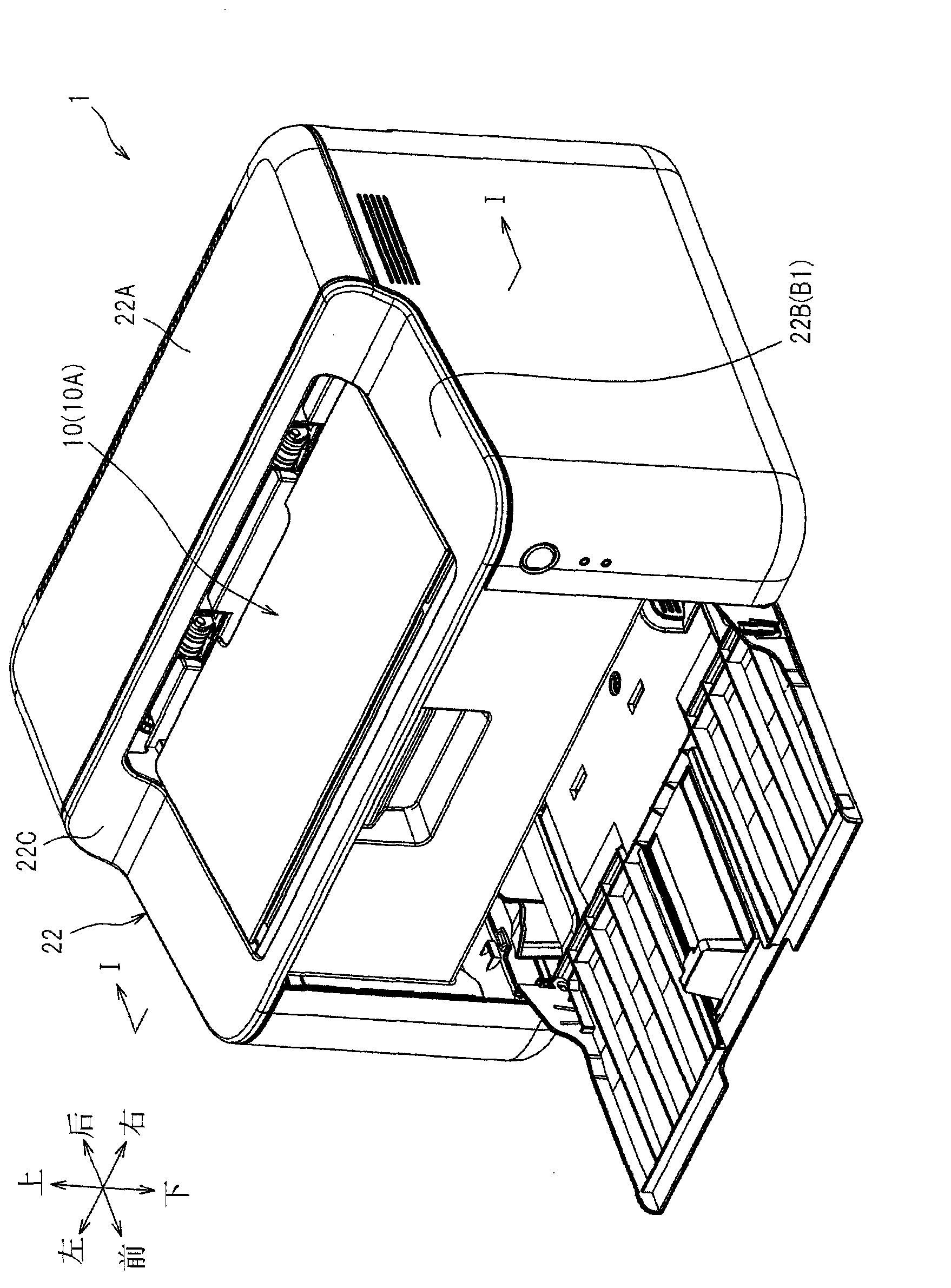
[0018] Such as figure 1 As shown, the laser printer 1 includes a main body 2 , a supply section 3 for supplying a sheet P as an example of a recording sheet, and an image forming section 4 for forming an image on the sheet P. ...


PUM


Abstract

An image forming apparatus (1) includes an ejection tray (9) including a support portion (94a), a plurality of ejection rollers (8) having a nip portion, and a tray cover (10) having a first surface and a second surface and being configured to move between an extended position where the first surface faces upward and a covering position where the tray cover is supported by the support portion to cover an upper surface of the ejection tray and the second surface faces upward. When the tray cover is in the covering position, an upstream end portion of the second surface of the tray cover in a sheet ejection direction is disposed in a position closer to the nip portion than the upper surface of the ejection tray and lower than the nip portion such that a leading end of the recording sheet ejected from the nip portion passes on or over the second surface.

Description

technical field [0001] The present invention relates to an image forming apparatus including a tray cover for covering a discharge tray. Background technique [0002] A known image forming apparatus includes a discharge tray, and a tray cover rotatably mounted on the discharge tray and rotatable between a covering position and an extended position. More specifically, in such an image forming apparatus, when the tray cover is in the covering position, the end of the tray cover is located above the sheet discharge opening (an opening substantially at the same level as the nip of the discharge roller). [0003] However, in such an image forming apparatus, since the end portion of the tray cover is located above the discharge roller nip, if the user accidentally gives a print instruction while the tray cover is in the cover position, the output from the discharge roller nip Ejected sheets may touch the lower surface of the tray cover and become jammed. Contents of the inventi...

Claims


Application Information

Patent Timeline
Patent Type & Authority Applications(China)
IPC IPC(8): B65H29/20B65H31/00G03G15/00
CPCB65H29/125B65H2405/1117B65H29/14B65H2405/1124B65H2301/512565B65H2601/255G03G15/6552B65H31/02B65H2402/441B41J13/106B65H2601/111B41J29/13B65H2801/12
Inventor 山本浩洋
Owner BROTHER KOGYO KK
Why Eureka
Try Eureka