Constant force cupping

A constant force, tank technology, applied in the direction of suction equipment, etc., can solve the problems of easy failure, complicated cupping operation, etc., and achieve the effect of no safety hazard

Inactive Publication Date: 2013-08-07
孙德修
View PDF5 Cites 0 Cited by
  • Summary
  • Abstract
  • Description
  • Claims
  • Application Information

AI Technical Summary

Problems solved by technology

[0005] The invention proposes a constant force cupping, which solves the p

Method used


Image

  • Constant force cupping
  • Constant force cupping
  • Constant force cupping

Examples


Embodiment 1

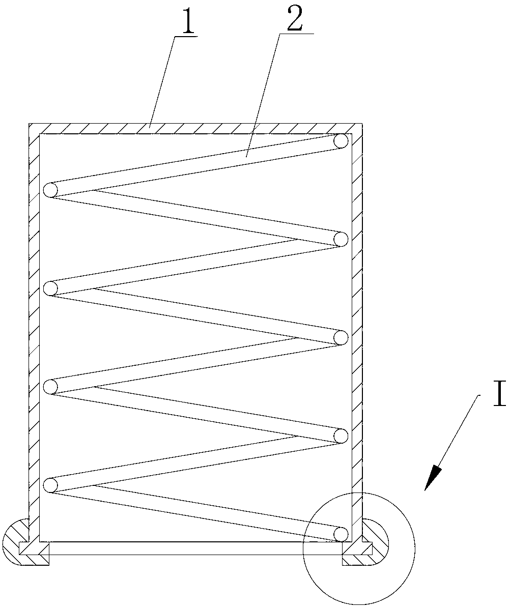
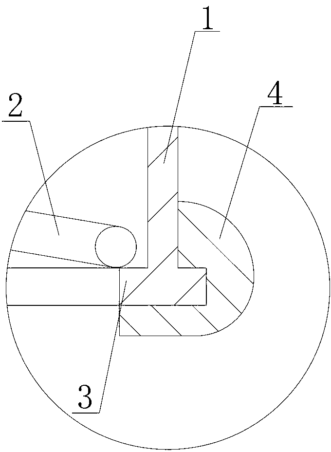
[0026] Such as figure 1 and figure 2 Commonly shown is an embodiment of the constant force cupping of the present invention, which includes an elastic tank body 1, the tank body 1 can be made of rubber or latex material, and its shape can be cylindrical or square shape etc.

[0027] The inside of the tank body 1 is provided with an elastic body for restoring the tank body 1 to its original state. The elastic body here is a compression spring 2, and the compression spring 2 realizes its function through the following structure:

[0028] The inner wall of the tank body 1 is provided with a position-limiting boss 3, and the clip spring 2 is vertically arranged, and its upper end leans against the top of the tank body 1, and its lower end leans against the position-limiting boss 3, so that when the tank body 1 is When compressed, the compression spring 2 is compressed at the same time, and the compression spring 2 produces an elastic force on the tank body 1 to restore it to it...

Embodiment 2

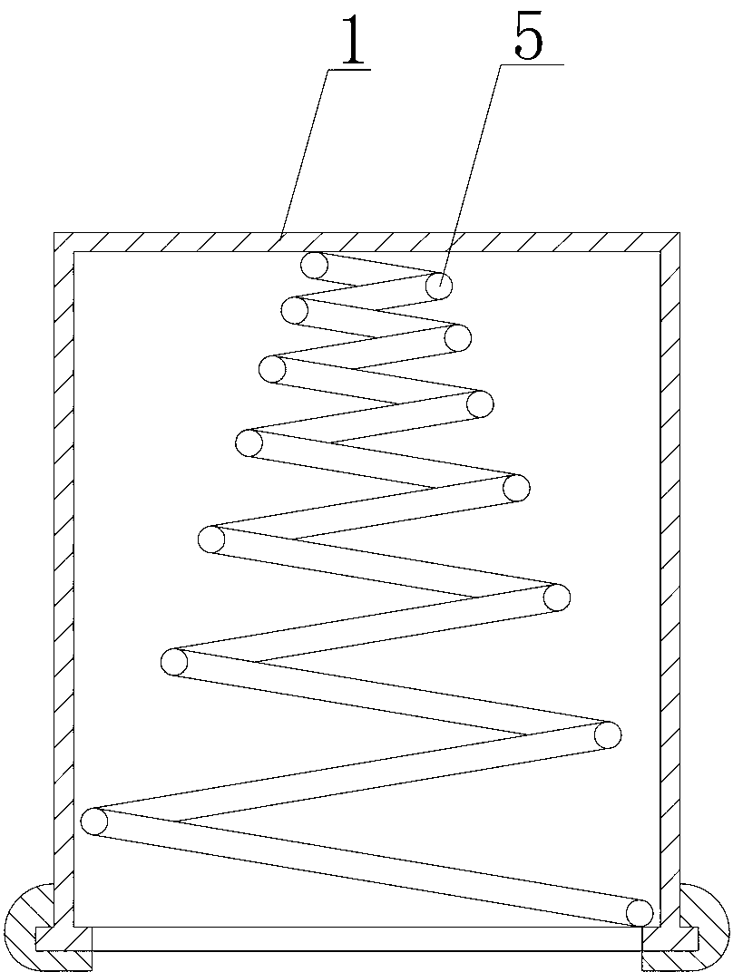
[0033] Such as image 3 Shown, is another embodiment of the constant force cupping of the present invention, and it and figure 1 The difference is that the elastic body in this embodiment uses a conical compression spring 5, the tip of which leans against the top of the tank body 1, and the larger end leans against the limit boss 3, which can also make the tank Body 1 restores its original shape. The rest of the structure in this example is the same as figure 1 are the same and will not be repeated here.

[0034] The method of using the constant force cupping is:

[0035] The operator compresses the tank body 1 and the compression spring 2 to a certain extent, and then buckles the tank body 1 at the place where cupping is required. After releasing the hand, the tank body 1 tends to return to its original shape under the elastic force of the compression spring 2 , at this time, a negative pressure is generated in the tank body 1, so that the tank body 1 is adsorbed on the s...


PUM


Abstract

The invention provides a constant force cupping. The constant force cupping comprises a cupping body which has certain elasticity and an elastomer which is used for enabling the cupping body to be rehabilitated is arranged inside the cupping body. When the constant force cupping is used, the cupping body is compressed with a certain degree through an operator, then the cupping body is buckled on the skin needs to be performed cupping and the cupping generates certain negative pressure under the function of the elastomer which is inside the cupping when a hand is loosen, so that the cupping is firmly absorbed on the skin and a constant absorption force is formed between the cupping body and the skin under the function of the elastomer to enable the cupping body not to fall off. The constant force cupping has the advantages of solving the problems that the cupping operation in the prior art is complex and is easy to lose effectiveness, being simple in operation and convenient to use, having no safety incidents and being capable of adjusting the size of suction according to the personal requirement of an operator and good in practicality.

Description

technical field [0001] The invention relates to the technical field of cupping, in particular to a constant force cupping. Background technique [0002] Cupping therapy (commonly known as cupping) uses the jar as a tool to remove the air in the jar by means of burning and squeezing to create a negative pressure, so that the jar is adsorbed on the specific cupping site (affected area, acupoint) on the body surface, causing extensive stimulation and local congestion. or blood stasis, so as to achieve the purpose of preventing and curing diseases and strengthening the body. [0003] With the continuous development of cupping technology, existing cupping therapy mainly includes cupping type, rotating type, sucking stick type, etc., but these several forms of cupping therapy all have deficiencies: [0004] For the cupping type, since it needs to use fire to bake the air in the tank, it is not only dangerous to use, but also because the heat is not easy to control, once the heat ...

Claims


Application Information

Patent Timeline
IPC IPC(8): A61M1/00
Inventor 孙德修
Owner 孙德修
Why Eureka
Try Eureka