Circular tube form tracking laser cutting machine

A laser cutting machine, tracking technology, applied in the direction of laser welding equipment, welding equipment, metal processing equipment, etc., can solve the problems of product scrapping, cutting position offset, confusion, etc., to improve processing accuracy and production efficiency, reduce The effect of scrap rate and accurate processing

Active Publication Date: 2015-04-22
SUZHOU LEAD LASER TECH
View PDF8 Cites 0 Cited by
  • Summary
  • Abstract
  • Description
  • Claims
  • Application Information

AI Technical Summary

Problems solved by technology

Due to the irregularity of the pipe itself and the heat deformation during processing, the distal end of the pipe will swing when it is rotating, which cannot ensure that the centerline of the cutting head coincides with the center of the round pipe
The cutting head of the traditional circular tube laser cutting machine cannot follow the deformation and swing of the tube, resulting in offset and confusion of the cutting position, and even product scrapping

Method used


Image

  • Circular tube form tracking laser cutting machine
  • Circular tube form tracking laser cutting machine
  • Circular tube form tracking laser cutting machine

Examples


Embodiment

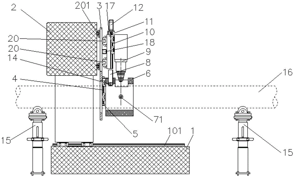
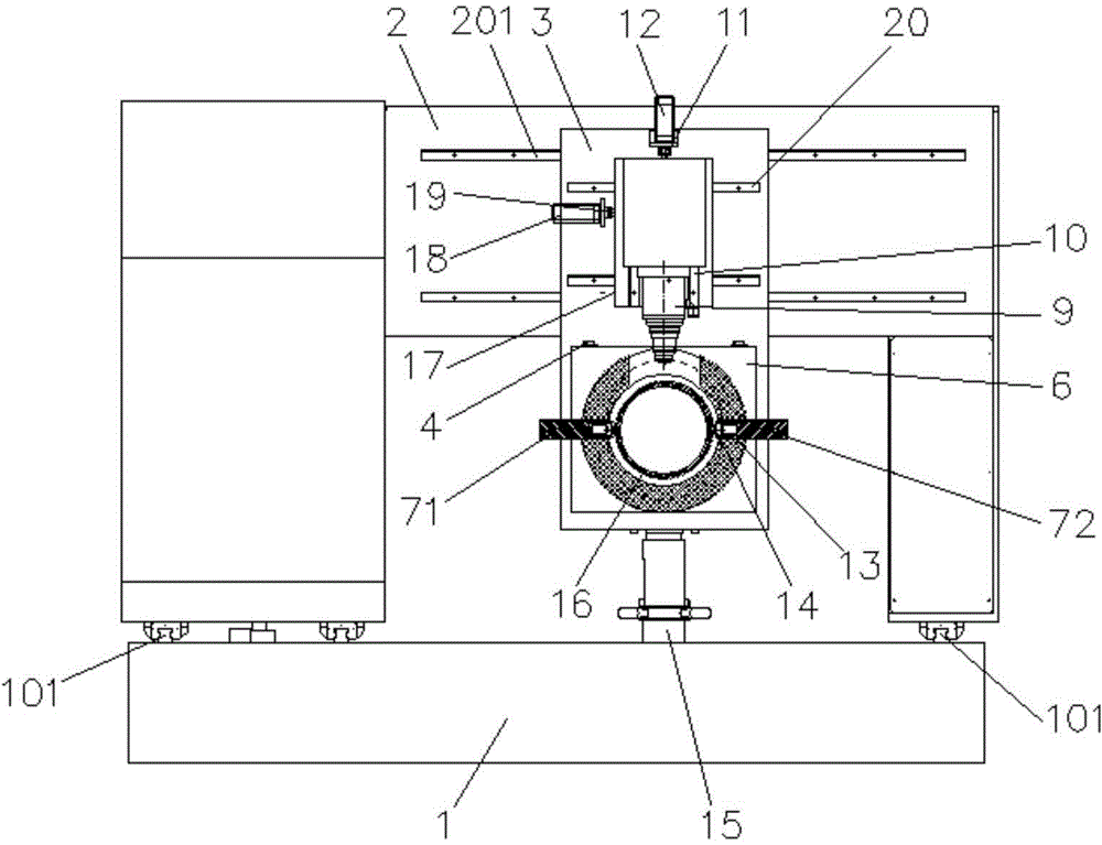
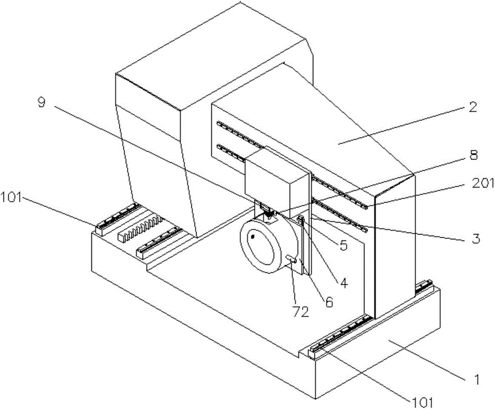
[0017] Embodiment: a circular tube shape tracking laser cutting machine, including at least two tube supports 15, a base 1, a beam 2, a first pallet 3, a second pallet 17, a cutting head 9, a support plate 6, a control device and the first, second, and third driving devices, and the three directions perpendicular to each other are respectively the X direction, the Y direction and the Z direction, and the Z direction is the vertical direction, and the two pipe fittings for supporting the pipe fitting 16 to be processed The support body 15 is fixedly positioned on both sides of the base 1 along the X direction. The base 1 is provided with a beam 2 that can slide back and forth linearly along the X direction. The first driving device is fixed on the base 1, and the first driving device drives the beam 2 along the X direction. direction movement, the first pallet 3 can be freely linearly reciprocated and positioned on the beam 2 along the Y direction, the second pallet 17 can be li...


PUM


Abstract

The invention discloses a circular tube forming tracking laser cutting machine. Two pipe supporting bodies are positioned on two sides of the X direction of a base; a first driving device drives a cross beam which can linearly slide in the X direction on the base; a first supporting plate can freely and linearly slide in the Y direction to be positioned on the cross beam; a second supporting plate can linearly slide in the Y direction to be positioned on the first supporting plate; a second driving device drives the second supporting plate to move; a cutting head can linearly sliding in the Z direction to be positioned on the second supporting plate; a third driving device drives the cutting head to move; a supporting plate can freely slide a set distance in the Z direction on the first supporting plate; a positioning hole in the X direction is formed in the supporting plate; a sensing device on the cutting head can sense the distance between a nozzle of the cutting head and a pipe to be machined and transmits the distance to a controller; and the controller controls the motion of the first, second and third driving devices. The machining of the cutting head is not affected by deformation and swinging of pipes, so that accurate machining is guaranteed, the machining precision and the production efficiency are improved, and the rejection rate is reduced.

Description

technical field [0001] The invention relates to a circular tube laser cutting machine, in particular to a circular tube shape tracking laser cutting machine. Background technique [0002] When cutting a round pipe, the cutting head is required to be above the round pipe, and the extension line of its center passes through the center of the round pipe. During the cutting process, the cutting head moves along the axis of the pipe, and the round pipe rotates around its axis. The rotary driving mechanism of the circular tube is located at one end of the circular tube. Due to the irregularity of the pipe itself and the heat deformation during the processing, the distal end of the pipe will swing when it is rotated, which cannot ensure that the centerline of the cutting head coincides with the center of the round pipe. The cutting head of the traditional circular tube laser cutting machine cannot follow the deformation and swing of the tube, resulting in offset, confusion, and e...

Claims


Application Information

Patent Timeline
Patent Type & Authority Patents(China)
IPC IPC(8): B23K26/38B23K26/08
Inventor 王瑞延许广军
Owner SUZHOU LEAD LASER TECH
Why Eureka
Try Eureka