Air compression energy storing device for road

A compressed air energy storage and road technology, applied in the direction of liquid variable displacement machinery, piston pumps, machines/engines, etc., can solve the problems of low solar energy density, no energy utilization of vehicle rolling speed bumps, and inability to continuously provide energy supply, etc. , to achieve the effect of improving the safety factor

Inactive Publication Date: 2013-08-07
王晨光
View PDF9 Cites 6 Cited by
  • Summary
  • Abstract
  • Description
  • Claims
  • Application Information

AI Technical Summary

Problems solved by technology

Solar energy also has problems such as low energy density and inability to provide continuous energy supply.
On the highway, there are many road sections that need to limit the speed and set up speed bumps, and there are thousands of vehicles passing by on the speed bumps. At present, there is no device that can use the energy of vehicles rolling over the speed bumps.

Method used


Image

  • Air compression energy storing device for road
  • Air compression energy storing device for road

Examples


Embodiment Construction

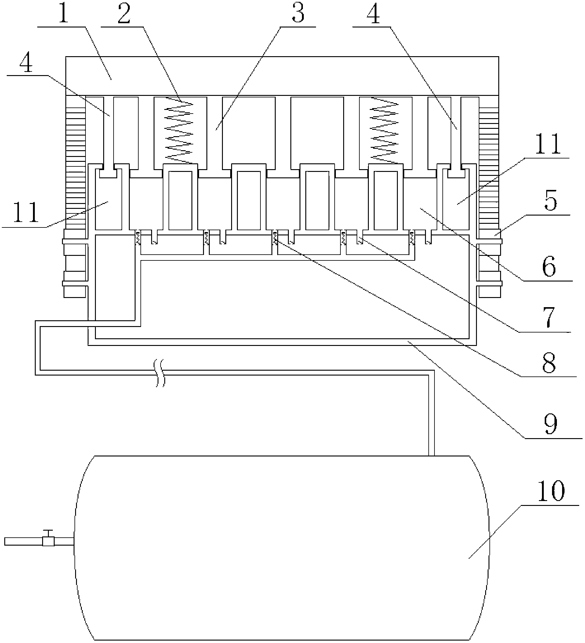
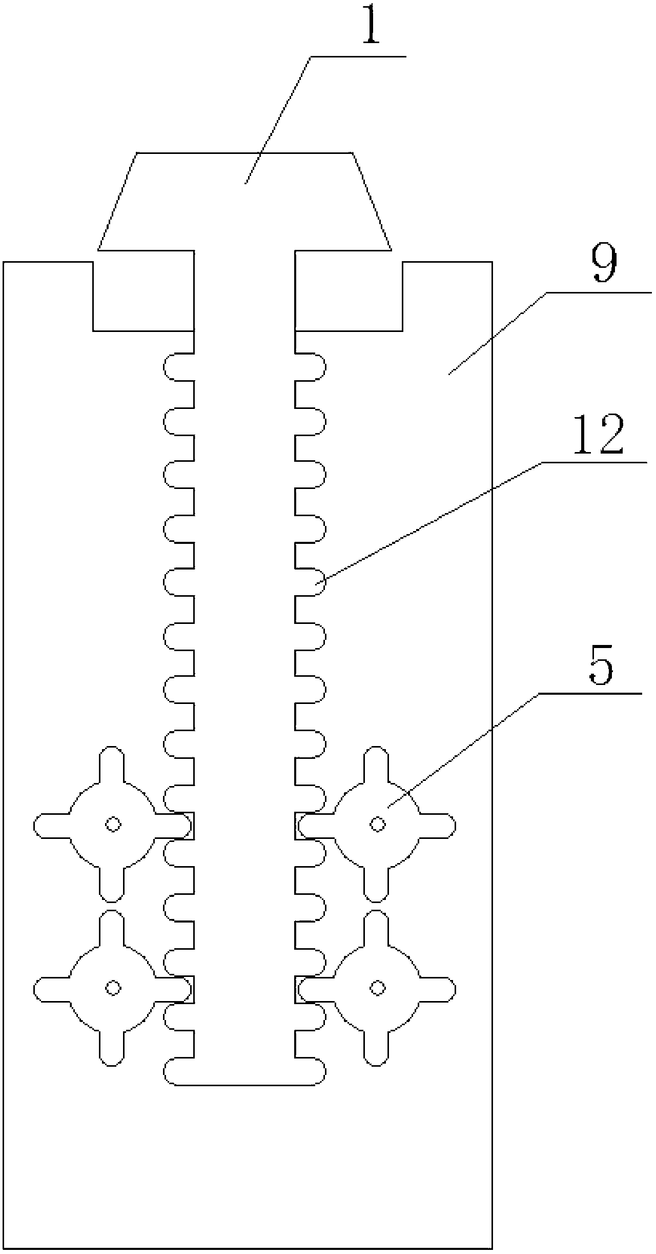
[0011] Such as figure 1 with figure 2 As shown, the road compressed air energy storage device includes an air storage tank, which is characterized in that: it also includes an compressed air beam 1 and a base 9, and a plurality of pistons 3 are arranged under the compressed air beam; The upper limit rod 4 and the compressed air beam rack 12; the base 9 is provided with an compressed air chamber 6 cooperating with the piston 3, and an air intake check valve 7 and an exhaust check valve 8 are arranged at the bottom of the compressed air chamber 6; The two ends of the base 9 are provided with a limit cavity 11 that cooperates with the upward limit rod 4 and a positioning gear 5 that cooperates with the air pressure beam rack 12; the piston 3 is located in the air pressure chamber 6; between the base 9 and the air pressure beam 1 is provided with a return spring 2; the upward limit rod 4 is located in the limit chamber 11; the compressed air beam rack 12 is located between two r...


PUM


Abstract

The invention provides an air compression energy storing device for a road and belongs to the technical field of compressed air preparation. The air compression energy storing device aims at preparing compressed air by utilizing energy produced by crushing of a deceleration strip by vehicles in a road section on the road requiring arranging the deceleration strip. The air compression energy storing device comprises an air storing tank and is characterized by further comprising an air compression beam and a base. A plurality of pistons are arranged under the air compression beam. An up limit rod and an air compression beam rack are sequentially arranged under two ends of the air compression beam from inside to outside. The base is provided with an air compression chamber matched with the pistons. An air feeding one-way valve and an air discharging one-way valve are arranged at the bottom of the air compression chamber. A limit cavity matched with the up limit rod and location gears matched with the air compression beam rack are arranged at two ends of the base. A resetting spring is arranged between the base and the air compression beam. The air compression beam rack is located between two rows of location gears. The air storing tank is communicated with the air discharging one-way valve at the bottoms of the pistons through a pipe.

Description

technical field [0001] The invention belongs to the technical field of compressed air generating equipment, and in particular relates to a road compressed air energy storage device. Background technique [0002] Currently known energy conversion devices all use primary energy, such as coal, nuclear energy, water energy, wind energy, and solar energy. Coal and nuclear energy have problems of environmental pollution and safety control. And wind energy. Solar energy also has problems such as low energy density and inability to provide continuous energy supply. On the highway, there are many road sections that need to limit the speed and set speed bumps, and there are thousands of vehicles on the speed bumps. At present, there is no device that can utilize the energy of the vehicles rolling over the speed bumps. Contents of the invention [0003] The purpose of the present invention is to provide a road compressed air energy storage device that generates compressed gas by r...

Claims


Application Information

Patent Timeline
IPC IPC(8): F04B35/06
Inventor 王晨光
Owner 王晨光
Why Eureka
Try Eureka