Container for containing liquid

A liquid and container technology, applied in the direction of buoy liquid level indicator, etc., can solve problems such as false alarms, and achieve the effect of avoiding false alarms

Inactive Publication Date: 2013-08-07
LIUZHOU LIUGONG EXCAVATORS +2
View PDF4 Cites 10 Cited by
  • Summary
  • Abstract
  • Description
  • Claims
  • Application Information

AI Technical Summary

Problems solved by technology

[0003] The object of the present invention is to provide a container for containing liquid which can avoid the

Method used


Image

  • Container for containing liquid
  • Container for containing liquid
  • Container for containing liquid

Examples


Embodiment 1

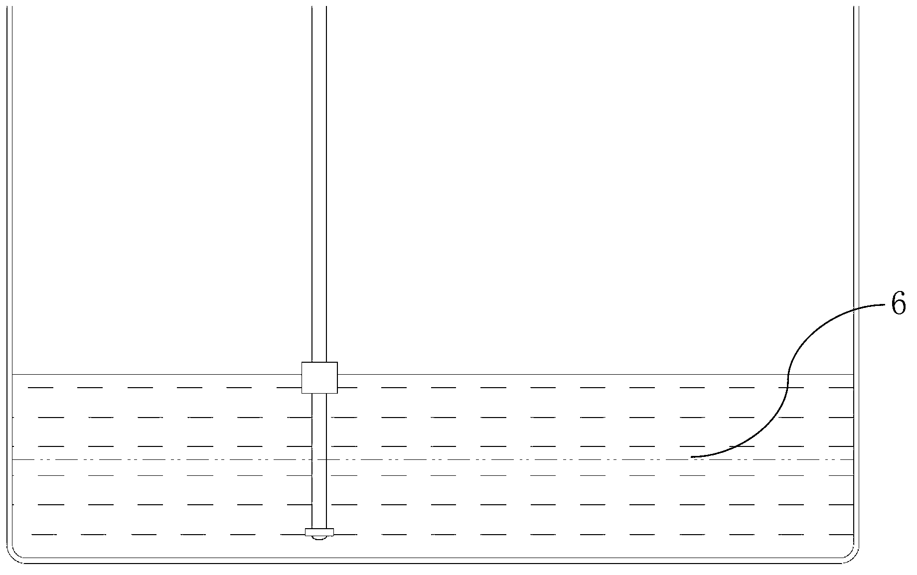
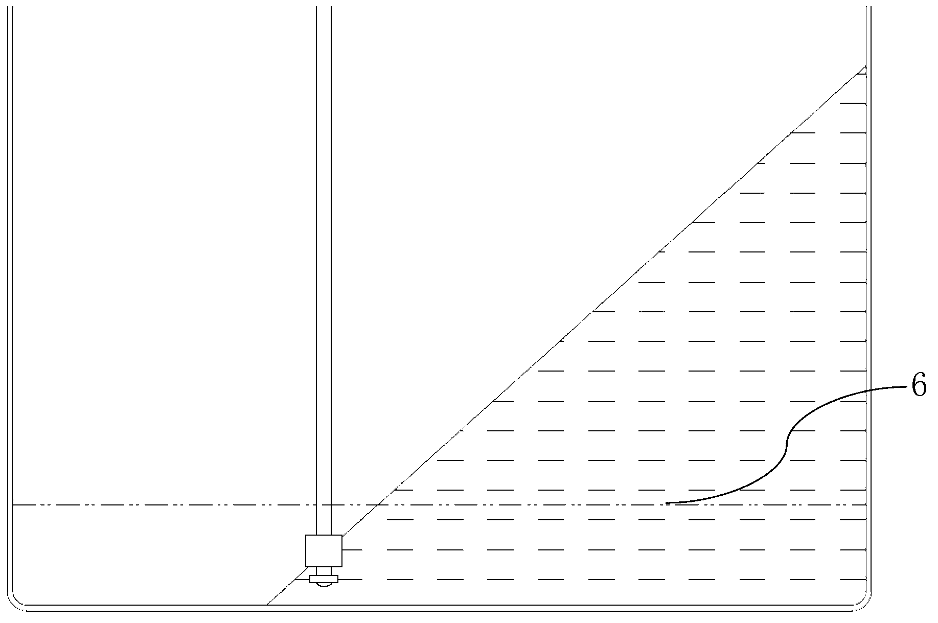
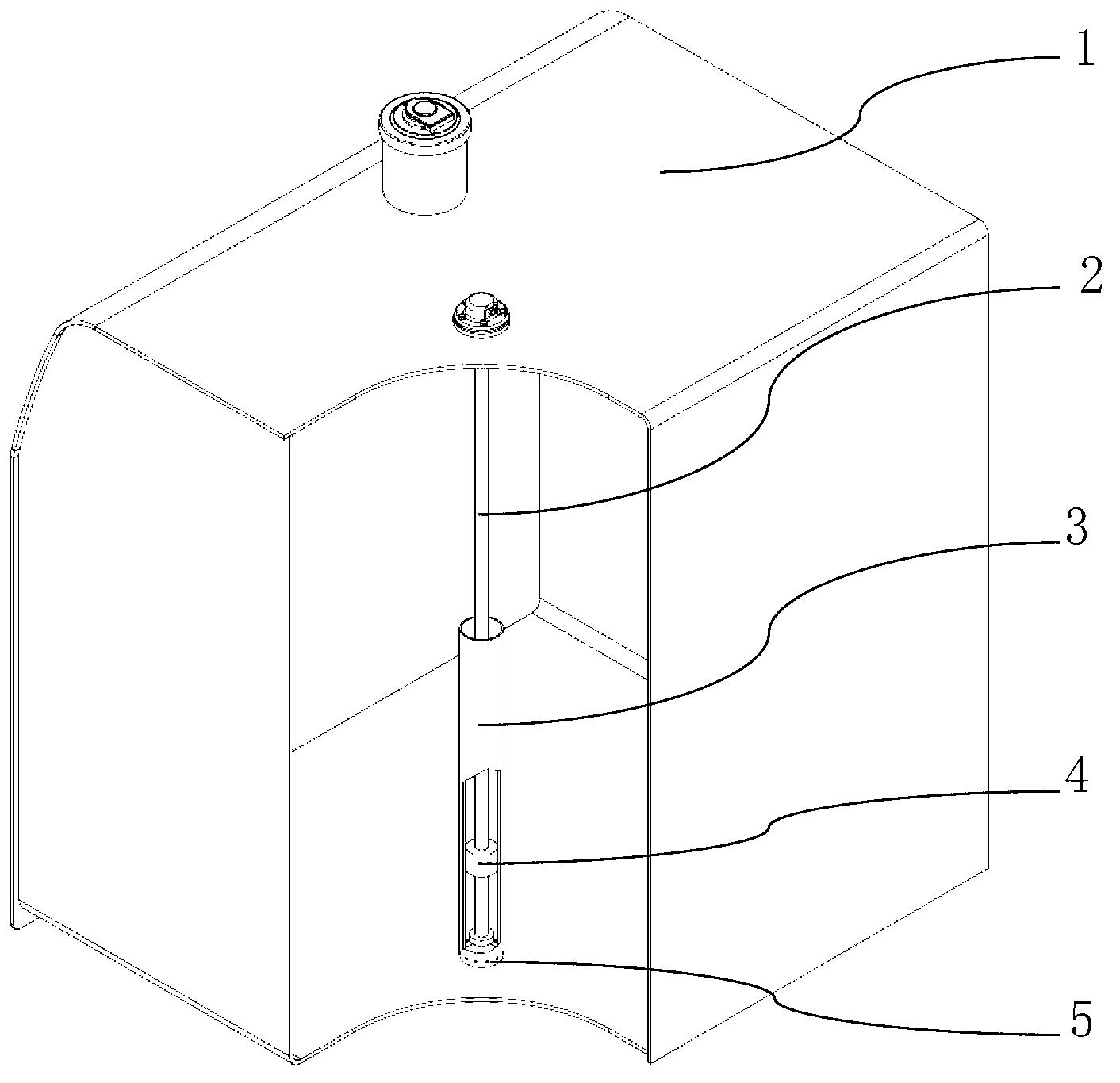
[0025] like Figure 3 to Figure 6 As shown, in this embodiment, the container containing the liquid includes a container body 1, and a liquid level sensor is arranged in the container body. The liquid level sensor includes an induction body 2 and an induction float 4. The induction body 2 is columnar and vertical Set in the container body 1, the induction float 4 is set on the induction body 2, and its equivalent density is lower than the density of the liquid contained in the container body, so that the induction float 4 can float on the liquid surface and move up and down with the induction body 2 float. The magnetic properties of the sensing float 4 conduct the internal resistance of the sensing body to achieve different resistance values ​​at different liquid levels, which are converted into liquid level signals through a certain algorithm, and the height of the liquid level is obtained to further obtain the liquid capacity in the container body. In the container body, a ...

Embodiment 2

[0027] like Figure 7As shown, in this embodiment, the liquid level sensor includes a cylinder, a sensing float, and a cylinder, and a sensing device is arranged inside the cylinder, and the sensing float is sleeved on the cylinder, and floats up and down with the height of the liquid level. And interact with the liquid level sensing device 8 in the column to generate a liquid level signal, and the top of the column is fixedly connected with the top cover 7 as the head of the liquid level sensor. The upper end of the cylinder 3 is also fixedly connected with the top cover 7 by bolts, the cylinder 9 is located in the cylinder 3, the upper part of the cylinder 3 communicates with the outside of the cylinder, and the lower part of the cylinder 3 communicates with the outside of the cylinder with a damping hole 5 . In this embodiment, the liquid level sensor is vertically installed in the container containing the liquid. When the container does not vibrate violently, that is, the...

Embodiment 3

[0029] like Figure 8 As shown, compared with Embodiment 2, the difference is that the liquid level sensor in this embodiment does not have a cylinder in the inner cavity of the cylinder 3, and the sensing device 8 is directly arranged in the cylinder wall of the cylinder 3, and the cylinder 3. It is fixedly connected with the head of the liquid level sensor, that is, the top cover 7. In this embodiment, the upper part of the cylinder body can also be an integrated structure with the head of the liquid level sensor, and a detachable bottom cover is provided at the bottom of the cylinder body to facilitate the loading and unloading of the sensing float.


PUM


Abstract

The invention relates to a container for containing liquid and aims to avoid the defect that as for a current container with a liquid level sensor, the liquid level sensor has high probability of giving a false alarm. The container provided by the invention comprises a container body with a liquid level sensor, wherein the liquid level sensor comprises a vertical columnar inductor and an induction float block sleeved on the inductor and being capable of sliding up and down; a cylinder body is vertically arranged in the container body and is provided with a lower part connected with the bottom of the container body; the lower end of the inductor is positioned in the cylinder body, and the induction float block can move up and down in the cylinder body; the height of the cylinder body is larger than the lowest liquid level height causing the liquid level sensor to give an alarm; and a damping hole is formed in the lower end of the cylinder body and communicated with the outside of the cylinder body. According to the invention, the liquid height of the cylinder body does not change with the changes of the liquid level outside the cylinder body, caused by various oscillation, so that the real height close to that of the still liquid can be detected out even if the liquid level in the container body is subject to serious oscillation, so as to avoid false alarm.

Description

technical field [0001] The invention relates to a container for containing liquid and a liquid level sensor, in particular to a container for containing liquid and a liquid level sensor with the function of preventing false alarm of liquid level. Background technique [0002] Liquid level sensors are usually installed in containers containing liquids such as fuel tanks, hydraulic oil tanks, and water radiators of existing construction machinery to detect the liquid level in the container body in real time. When the detected liquid level is lower than the set value, An alarm signal will be sent to remind the user to deal with abnormal working conditions in time. The liquid level sensor installed in the container body is usually composed of a columnar induction body erected in the container and an induction float set on the induction body. The equivalent density of the induction float is less than the density of the liquid in the container, and the induction float floats on T...

Claims


Application Information

Patent Timeline
IPC IPC(8): G01F23/30
Inventor 诸葛敏苏永志冯立霞
Owner LIUZHOU LIUGONG EXCAVATORS
Why Eureka
Try Eureka