
Laser radar device and method for measuring target object distance through device

A technology of laser radar and target objects, which is applied in the field of laser radar devices to measure the distance of target objects, can solve the problem that the resolution cannot be improved at the same time, and achieve the effects of improving detection sensitivity, reducing noise, and preventing false alarms

Inactive Publication Date: 2014-02-12
INST OF SEMICONDUCTORS - CHINESE ACAD OF SCI
View PDF2 Cites 19 Cited by
  • Summary
  • Abstract
  • Description
  • Claims
  • Application Information

AI Technical Summary

Problems solved by technology

[0004] In order to solve the above problems, the main purpose of the present invention is to provide a laser radar device with high resolution, large dynamic range and simple structure and a method for measuring the distance of the target object by using the device, so as to solve the problem that the working distance and the distance resolution cannot be improved simultaneously. The problem

Method used


Image

  • Laser radar device and method for measuring target object distance through device
  • Laser radar device and method for measuring target object distance through device

Examples


Embodiment Construction

[0029] In order to make the object, technical solution and advantages of the present invention clearer, the present invention will be described in further detail below in conjunction with specific embodiments and with reference to the accompanying drawings.

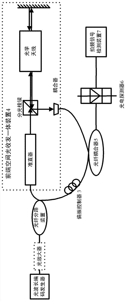
[0030] like figure 1 as shown, figure 1 It is a schematic structural diagram of a laser radar device with wavelength encoding provided by the present invention, which includes an optical wavelength encoding generator 1, an optical fiber branching device 2, a polarization controller 3, a front-end space optical transceiver integrated device 4, a fiber coupler 5, a photoelectric Detector 6 and beat frequency signal detection device 7, wherein:

[0031] The optical wavelength code generator 1 is used to generate a coded optical pulse signal including a detection optical pulse signal and a reference optical pulse signal, and transmit it to the optical fiber branching device 2 . The optical fiber branching device 2 is used t...


PUM


Abstract

The invention discloses a laser radar device for wavelength encoding and a method for measuring a target object distance through the device. The device comprises a light wavelength encoding generator, an optical fiber shunt device, a polarization controller, a front end space light receiving and emitting integrated device, an optical fiber coupler, a photoelectric detector and a beat frequency signal detection device. The light wavelength encoding generator generates a detection light pulse and a reference light pulse, a detection light pulse signal enters the front end space light receiving and emitting integrated device along an optical fiber after entering the optical fiber shunt device, and then the detection light pulse signal radiates a target object after being emitted through a collimator, a beam splitter prism and a coupler. After diffusion light on the target object is collected by an optical antenna, the diffusion light enters the optical fiber coupler through the beam splitter prism and the coupler. A reference light pulse signal enters the optical fiber coupler and enters the photoelectric detector along with a scattered signal optical pulse for beating after passing through the polarization controller. The device and the method solve the problem that the work distance and distance resolution of traditional laser radar can not be improved at the same time, and automated signal detection can be achieved.

Description

technical field [0001] The invention relates to the field of laser radar, in particular to a wavelength coded laser radar device and a method for measuring the distance of an object by using the device. Background technique [0002] Lidar uses a laser to convert electrical pulses into light pulses and emits them. The optical receiver then restores the light pulses reflected from the target into electrical pulses and sends them to the display and processing unit. The range resolution of LiDAR can be significantly improved using very short pulses, but for peak power limited systems, using short pulses reduces the average transmit power, significantly affecting the signal-to-noise ratio of the received signal. Therefore, the working distance and distance resolution of lidar cannot be improved at the same time. Contents of the invention [0003] (1) Technical problems to be solved [0004] In order to solve the above problems, the main purpose of the present invention is to ...

Claims


Application Information

Patent Timeline
Patent Type & Authority Applications(China)
IPC IPC(8): G01S17/08
CPCG01S7/481G01S7/4817G01S17/10
Inventor 祝宁华佟有万刘建国陈伟
Owner INST OF SEMICONDUCTORS - CHINESE ACAD OF SCI
Learn More