Self-adaptive butt-joint automatic charger

An automatic charging device and self-adaptive technology, applied in the direction of circuit devices, battery circuit devices, connecting device components, etc., can solve the problems that mobile robots cannot be automatically charged, cannot be accurately controlled, and have high cost, and achieve simple structure and accurate control , the effect of low cost

Active Publication Date: 2013-08-07
HARBIN INST OF TECH
View PDF5 Cites 20 Cited by
  • Summary
  • Abstract
  • Description
  • Claims
  • Application Information

AI Technical Summary

Problems solved by technology

[0003] In order to solve the problem that the existing mobile robot cannot be automatically charged, the existing mobile robot automatic charging device is expensive and cannot be accurately controlled, and further proposes an adaptive docking automatic charging device

Method used


Image

  • Self-adaptive butt-joint automatic charger
  • Self-adaptive butt-joint automatic charger
  • Self-adaptive butt-joint automatic charger

Examples


specific Embodiment approach 1

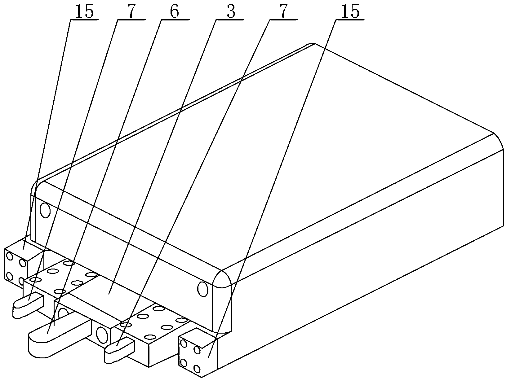
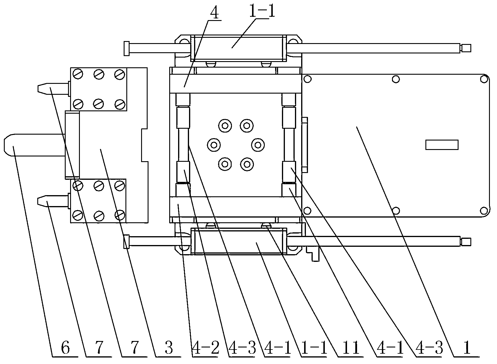
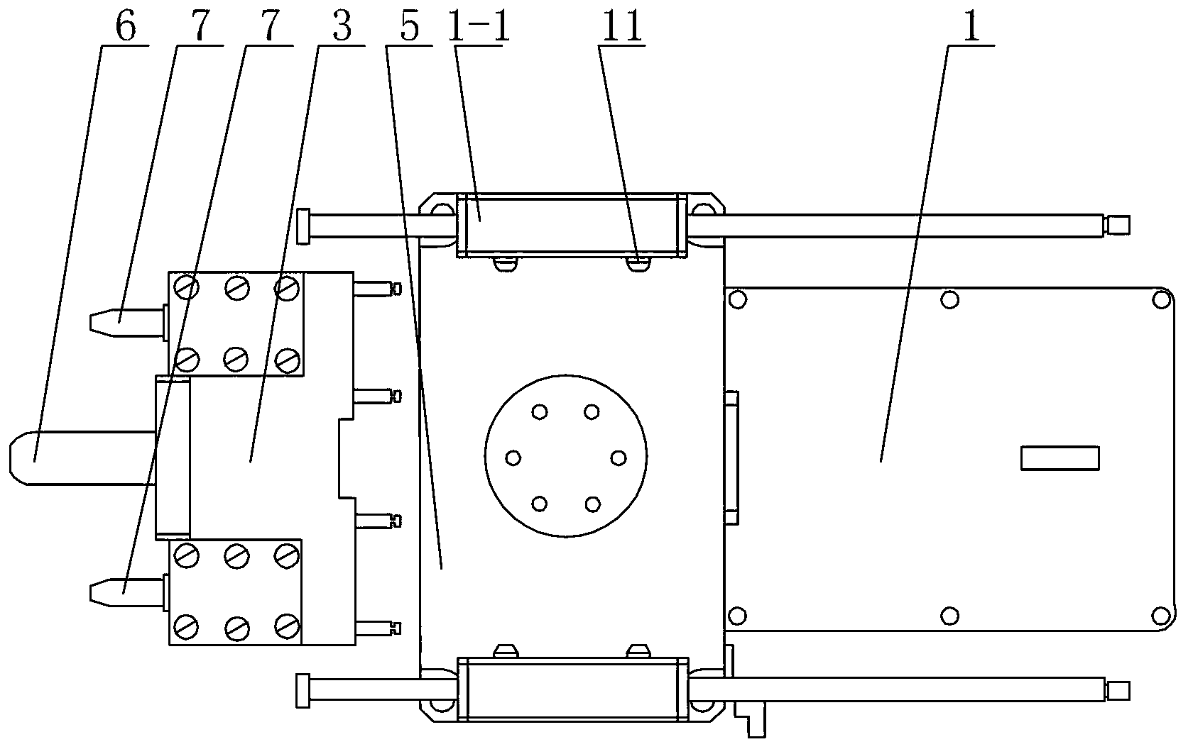
[0007] Specific implementation mode one: combine Figure 1 to Figure 5 Describe this embodiment, an adaptive docking automatic charging device described in this embodiment includes a charging body and a power receiving body, and the charging body includes a charging base 1, a charging contact platform 3, a horizontal movement mechanism 4, and a central rotation mechanism 5 1. Positioning guide head 6 and two charging contacts 7, the power receiving body includes a power receiving base 8, a sensor 9 and two power receiving contacts 10, and a stopper is respectively provided on both sides of the upper surface of the charging base 1 1-1, and the center line of each block 1-1 along the length direction is parallel to the center line of the charging base 1 along the length direction, the central rotation mechanism 5 is installed on the upper surface of the charging base 1, and the horizontal movement mechanism 4 is installed On the upper surface of the central rotating mechanism 5,...

specific Embodiment approach 2

[0009] Specific implementation mode two: knot Figure 1 to Figure 5 Describe this embodiment, the horizontal movement mechanism 4 of an adaptive docking automatic charging device described in this embodiment includes two round rods 4-1, two sliders 4-2 and four springs 4-3, two sliders Blocks 4-2 are arranged side by side in parallel, two round rods 4-1 are arranged side by side in parallel between two sliders 4-2, two round rods 4-1 and two sliders 4-2 form a rectangular frame, each The two ends of each round rod 4-1 are equipped with a spring 4-3 respectively, and the charging contact platform 3 is installed on the two round rods 4-1, and the charging contact platform 3 can be horizontal along the two round rods 4-1. move.

[0010] The technical effect of this embodiment is: the charging contact platform 3 can move freely horizontally on the two round rods 4-1 so that the two charging contacts 7 can be inserted into the corresponding power receiving contacts 10, and the fou...

specific Embodiment approach 3

[0012] Specific implementation mode three: combination Figure 1 to Figure 5 To illustrate this embodiment, two spring stop pins 11 are arranged side by side between the inner side of each block 1 - 1 of the self-adaptive docking automatic charging device and the side corresponding to the central rotation mechanism 5 .

[0013] The technical effect of this embodiment is: so set, the spring stop pin 11 can ensure that the central rotating mechanism 5 returns to its original position after the robot is fully charged.

[0014] Other components and connections are the same as those in the first embodiment.


PUM


Abstract

The invention relates to a charger, in particular to a self-adaptive butt-joint automatic charger. The purpose is to solve the problems that a conventional movable robot cannot be automatically charged, the manufacturing cost of a conventional automatic movable robot charger is high, and control is inaccurate. Two stop dogs are respectively arranged on two sides of the top surface of a charge base of the self-adaptive butt-joint automatic charger, a central rotating mechanism is mounted on the top surface of the charge base, a horizontal moving mechanism is mounted on the top surface of the central rotating mechanism, a charge contact platform is mounted on the horizontal moving mechanism, a positioning guide is mounted at the middle of the mounting surface of the charge contact platform, two charge contact points are respectively mounted on two sides of the positioning guide, the middle of the power-receiving surface of a power-receiving base is provided with a power-receiving positioning socket, two power-receiving contact points are respectively mounted by two sides of the power-receiving positioning socket, a sensor is mounted in the power-receiving positioning socket, and the positioning guide on the charge body can be plugged into the power-receiving positioning socket on the power-receiving base. The self-adaptive butt-joint automatic charger is used for charging movable robots.

Description

technical field [0001] The invention relates to a charging device, in particular to an adaptive docking automatic charging device. Background technique [0002] A mobile robot is a robot that walks automatically to complete a specific job. The characteristic of this robot is that it can perform the job as instructed. When the existing mobile robot utilizes the battery to act and cause the battery to discharge, in order to make the battery provide the electric energy required for the action, the user needs to personally connect the battery to an additional charging stand for charging. Therefore, the existing mobile robots have the disadvantage of being unable to charge automatically without supervision. In order to solve such disadvantages, a method of guiding the mobile robot to the charging stand and a method of trying to connect the contacts have been proposed recently. However, the guiding method is not only It requires the difficult technology of the robot, and it also ...

Claims


Application Information

Patent Timeline
Patent Type & Authority Applications(China)
IPC IPC(8): H02J7/00H01R13/629G05D3/00
Inventor 赵杰杜志江李瑞峰王伟东赵立军王珂
Owner HARBIN INST OF TECH
Why Eureka
Try Eureka