

Led lighting device including a highly-efficient power supply
A technology of LED lighting and power supply, which is applied in the direction of lighting devices, electric light sources, electroluminescent light sources, etc., can solve the problems of power supply efficiency reduction, achieve the effects of reducing power consumption, improving reliability, and reducing power consumption
- Summary
- Abstract
- Description
- Claims
- Application Information
AI Technical Summary
Problems solved by technology
Method used
Image

Examples
Embodiment 1
[0033] The first embodiment of the present invention relates to a high-efficiency LED lighting device, which is characterized in that: the residual voltage consumed by the current source that limits the load current is added to both ends of the power supply capacitor of the controller, so that the power supply capacitor can be charged by recycling the load current Higher efficiency.
[0034] Combine below figure 2 Embodiment 1 of the present invention will be described.
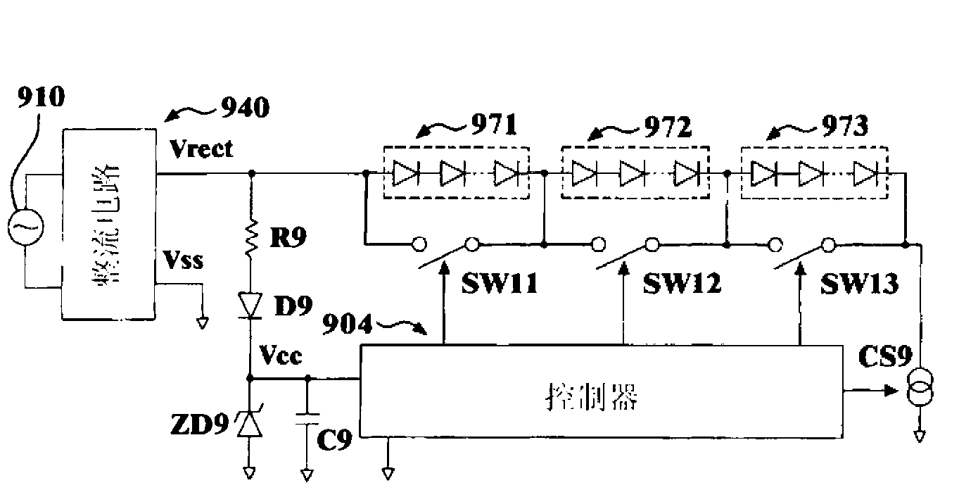
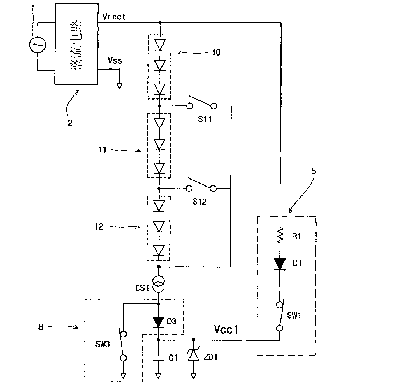
[0035] Such as figure 2 As shown, the LED lighting device of the first embodiment of the present invention includes the following parts: an AC power supply 1 that supplies an AC voltage; a rectifier circuit 2 that converts the AC voltage supplied by the AC power supply 1 into a DC rectified voltage Vrect; The first LED light-emitting block 10 to the third LED light-emitting block 12 driven by the rectified voltage Vrect; the first bypass switch S11 and the second bypass for bypassing the current of these ...
Embodiment 2
[0066] The second embodiment of the present invention is an embodiment described using specific numerical values.
[0067] Combine below Figure 2 to Figure 9 A second embodiment of the present invention will be described.
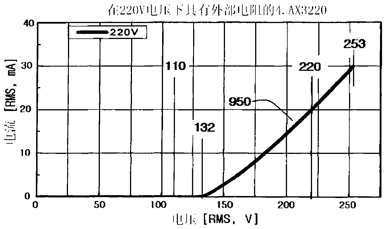
[0068] The second embodiment of the present invention is: the image 3 The shown LED array with voltage-current characteristics is divided into 10 equal parts to make a sub-light-emitting block, and the load of up to 11 sub-light-emitting blocks in series is applied to figure 2 A concrete example in the circuit.
[0069] At this time, a bypass switch should be set to prevent the circuit from flowing through each light-emitting block.
[0070] figure 2 The circuit shown shows an example of 3 light-emitting blocks. If it shows the general situation of adding a light-emitting block from 3 to 4, insert the light to be increased between the output terminal of the last light-emitting block n and the current source CS1 block (n+1), and the added bypass swi...
Embodiment 3
[0112] Combine below Figure 10 Circuit The third embodiment of the present invention will be described.
[0113] Figure 10 The circuit configuration shown is basically the same as figure 2 The circuits are the same, but the structure of the load current recycling charging circuit 8a is different, and the arrangement of switches for bypassing the load light-emitting block current is different.
[0114] To simplify the description, the following figure 2 Some descriptions of specific technologies are omitted, and only the differences are described.
[0115] Figure 10 The first difference of the circuit shown is that the structure of the load current recycling charging circuit 8a is the same as that of figure 2 The circuit is different. That is, the purpose of improving power supply efficiency by recycling the load current is the same, but the specific implementation methods are different.
[0116] Figure 10 In the circuit, there are two paths through which the cur...
PUM
 Abstract
Description
Claims
Application Information