Wireless power transmission device, method for controlling heat generated by wireless power transmission device, and production method for wireless power transmission device

A technology of wireless power transmission and heat control, applied in circuit devices, battery circuit devices, transmission systems, etc., can solve problems such as increased heat generation and shortened life of electronic parts

Inactive Publication Date: 2015-04-29
NITTO DENKO CORP
View PDF4 Cites 2 Cited by
  • Summary
  • Abstract
  • Description
  • Claims
  • Application Information

AI Technical Summary

Problems solved by technology

Furthermore, if the amount of heat generated in the wireless power transmission device becomes large, the life of electronic parts constituting the wireless power transmission device will be shortened.

Method used


Image

  • Wireless power transmission device, method for controlling heat generated by wireless power transmission device, and production method for wireless power transmission device
  • Wireless power transmission device, method for controlling heat generated by wireless power transmission device, and production method for wireless power transmission device
  • Wireless power transmission device, method for controlling heat generated by wireless power transmission device, and production method for wireless power transmission device

Examples


Embodiment approach

[0044] Embodiments of the wireless power transmission device, the heat generation control method of the wireless power transmission device, and the manufacturing method of the wireless power transmission device according to the present invention will be described below. First, the wireless power transmission device 1 used in this embodiment will be described.

[0045] (Structure of wireless power transmission device 1)

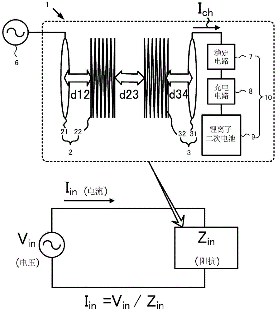
[0046] Such as figure 1 As shown, the wireless power transmission device 1 includes a power supply module 2 including a power supply coil 21 and a power supply resonator 22 , and a power receiving module 3 including a power receiving coil 31 and a power receiving resonator 32 . Furthermore, an AC power source 6 having an oscillation circuit for setting the driving frequency of electric power supplied to the power supply module 2 to a predetermined value is connected to the power supply coil 21 of the power supply module 2 , and to the power reception coil 31...

other Embodiment approach

[0142] In the description of the above-mentioned manufacturing method, the wireless headphone 200 was exemplified and described, but as long as it is a device equipped with a secondary battery, it can also be used in a tablet PC, a digital camera, a mobile phone, and an earphone-type music player. , hearing aids, sound collectors, etc.

[0143] In addition, in the above description, the case where the wireless power transmission device 1 is mounted on a portable electronic device is assumed to be described. However, the application is not limited to these small devices. Wireless charging systems for electric vehicles (EVs), smaller wireless intragastric cameras for medical use, etc.


PUM

PropertyMeasurementUnit
Resonant frequencyaaaaaaaaaa

Abstract

In the wireless power transmission apparatus (1), in which power is supplied by resonance phenomenon from a power-supplying module (2) to a power-receiving module (3) that is connected to a lithium ion secondary battery (9) capable of being charged by a constant current / constant voltage charging system, a variable parameter, which constitutes the power supply module and the power receiving module, is set such that the transmission characteristic value for the drive frequency of power supplied to the power-supplying module (2) exhibits double-hump characteristics. Thus, adjustment of the drive frequency sets the variation tendencies of the input impedance (Zin) of the wireless power transmission apparatus (1) during constant voltage charging to adjust the variation tendencies of the input current (I in ) of the wireless power transmission apparatus (1), and enables the heat generated by the wireless power transmission apparatus (1) to be controlled.

Description

technical field [0001] The present invention relates to a wireless power transmission device capable of controlling heat generation of the wireless power transmission device, a heat generation control method of the wireless power transmission device, and a manufacturing method of the wireless power transmission device. Background technique [0002] In recent years, notebook PCs (Personal Computers), tablet PCs, digital cameras, mobile phones, portable game consoles, headphone music players, wireless headphones, hearing aids, recorders, etc. Portable electronic devices are rapidly becoming popular. Furthermore, most of these portable electronic devices are equipped with rechargeable batteries, and need to be charged periodically. In order to simplify the charging operation of the rechargeable battery of the electronic device, the power supply technology (wireless power transmission technology that changes the magnetic field and transmits power) is used between the power supp...

Claims


Application Information

Patent Timeline
Patent Type & Authority Applications(China)
IPC IPC(8): H02J17/00H01M10/46H02J7/00
CPCH02J5/005H01M10/46H02J50/12H02J7/00302Y02E60/10H02J50/005H02J50/50H02J7/007192H04B5/0037
Inventor 畑中武蔵津田尚
Owner NITTO DENKO CORP
Why Eureka
Try Eureka