Test tube rack with vibrating-stirring functions and use method thereof

A technology of vibrating stirring and test tube racks, applied in the directions of test tube supports/clamps, mixer accessories, chemical instruments and methods, etc., can solve problems such as inconvenience, and achieve the effect of protecting test tubes and facilitating cleaning

Pending Publication Date: 2020-04-14
广西壮族自治区生态环境监测中心
View PDF0 Cites 1 Cited by
  • Summary
  • Abstract
  • Description
  • Claims
  • Application Information

AI Technical Summary

Problems solved by technology

In chemical experiments, the reaction of chemical agents in test tubes often requires certain conditions, such as shaking, suitable temperature, etc., and the current test tube rack is only used to place test tubes, which brings some inconvenience to the experiment

Method used


Image

  • Test tube rack with vibrating-stirring functions and use method thereof
  • Test tube rack with vibrating-stirring functions and use method thereof
  • Test tube rack with vibrating-stirring functions and use method thereof

Examples


Embodiment Construction

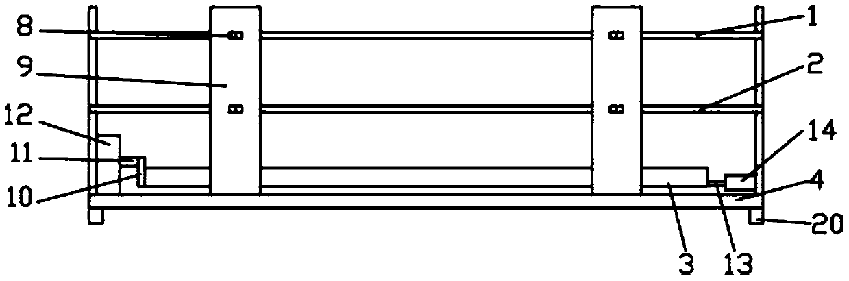
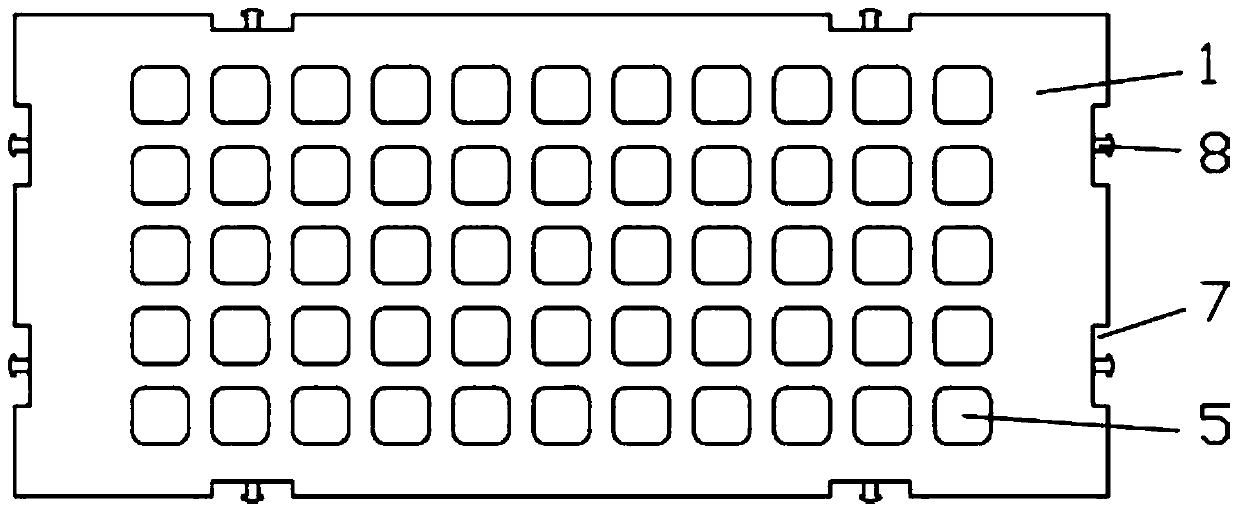
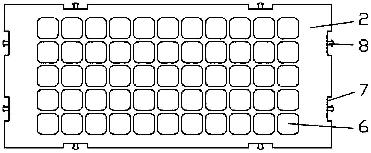
[0034] Combine below Figure 1-8 The present invention is further described, but the protection scope of the present invention is not limited to the content.

[0035] Wherein the same components are denoted by the same reference numerals. It should be noted that the words "front", "rear", "left", "right", "upper" and "lower" used in the following description refer to the directions in the drawings, and the words "inner" and "outer "respectively refer to directions toward or away from the geometric center of a specific component, and the drawings are all in a very simplified form and use inaccurate ratios, which are only used to facilitate and clearly assist the purpose of illustrating the embodiments of the present invention.

[0036] For the sake of clarity, not all features of an actual embodiment are described. In the following description, well-known functions and constructions are not described in detail since they would obscure the invention with unnecessary detail and ...


PUM


Abstract

The invention discloses a test tube rack with vibrating-stirring functions. The test tube rack comprises an upper limiting plate, a lower limiting plate, a vibrating plate and a bottom plate, a plurality of upper test tube holes are formed in the upper limiting plate, a plurality of lower test tube holes are formed in the lower limiting plate, side stabilizing plate grooves are formed in the front, rear, left and right side faces of the upper limiting plate and the lower limiting plate, the right side of a sliding rail fixing block is fixed to two side stabilizing plates located on the right side, the vibrating plate is located above the bottom plate, and test tube grooves are formed in the vibrating plate. The device has the beneficial effects that an telescopic control device is adoptedto control the vibrating plate to slide left and right to achieve the purpose of vibrating the test tubes, so that substances in the test tubes are uniformly mixed; the test tube rack has a heating function; the upper test tube holes are smaller than the lower test tube holes, so that violent collision between the test tubes and the limiting plates in the vibration process is avoided, the test tubes are protected, the limiting plate is detachable, so that the interior of the test tube rack can be cleaned conveniently; and a water collecting tank is arranged on the bottom plate, so that water is prevented from directly flowing on an experiment table.

Description

technical field [0001] The invention relates to a test tube rack with a vibration and stirring function and a using method thereof, belonging to the technical field of test equipment. Background technique [0002] The chemical laboratory is an important place to provide chemical experiment conditions and scientific inquiry. There are a large number of instruments in it: iron racks, test tube racks and other experimental tools. Among them, the test tube rack is a very common one. The test tube rack is the most basic experimental instrument for placing (sometimes the test tube can also be placed on the test tube rack to observe the phenomenon of a certain experiment) and drying the test tube. . In chemical experiments, the reaction of chemical agents in test tubes often requires certain conditions, such as shaking, suitable temperature, etc., but the current test tube rack is only used to place test tubes, which brings some inconvenience to the experiment. Contents of the ...

Claims


Application Information

Patent Timeline
Patent Type & Authority Applications(China)
IPC IPC(8): B01L9/06B01F11/00B01F15/06
CPCB01L9/06B01F31/00B01F2035/99B01F35/92
Inventor 覃华芳滕云梅黄增张少梅吕保玉许业梅潘艳
Owner 广西壮族自治区生态环境监测中心
Why Eureka
Try Eureka