Inertia-locking reactive bumper for motor vehicle

A vehicle, inertial technology, applied in the direction of bumpers, vehicle parts, vehicle safety arrangements, etc.

Active Publication Date: 2013-08-14
FORD GLOBAL TECH LLC
View PDF5 Cites 16 Cited by
  • Summary
  • Abstract
  • Description
  • Claims
  • Application Information

AI Technical Summary

Problems solved by technology

[0005] To address at least one of the problems of the prior art, the disclosed bumper system utilizes a deceleration-actuated trigger to selectively lock the bumper system during a high-energy collision, thereby allowing the bumper and strut (shattering) tank) absorbs crash energy, or allows the bumper beam to move rearwardly against spring force during a low energy crash

Method used


Image

  • Inertia-locking reactive bumper for motor vehicle
  • Inertia-locking reactive bumper for motor vehicle
  • Inertia-locking reactive bumper for motor vehicle

Examples


Embodiment Construction

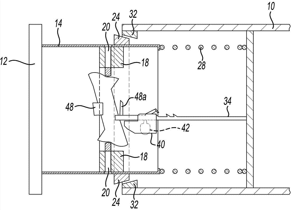
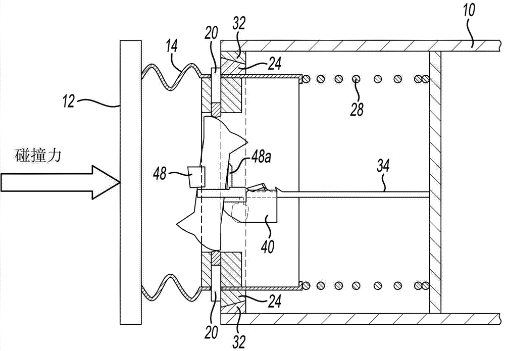
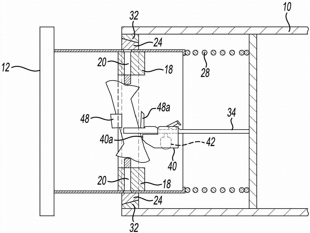
[0021] As required, specific embodiments of the present invention are disclosed herein; however, it is to be understood that the disclosed embodiments are merely exemplary of the invention, which may be embodied in various and alternative ways. The figures are not necessarily to scale; some features may be exaggerated or minimized to show details of particular components. Therefore, specific structural and functional details disclosed herein are not to be interpreted as limiting, but merely as a representative basis for teaching one skilled in the art to variously employ the present invention.

[0022] As used herein, the terms "automobile" and "motor vehicle" refer to any wheeled vehicle, on or off the road, and include (but are not limited to) cars, trucks (light and heavy), utility vehicles vehicles, crossover vehicles and construction equipment.

[0023] figure 1 with figure 2 The front portion of the frame rail 10 and the front bumper beam 12 are shown schematically. ...


PUM


Abstract

An energy-absorbing front end structure for a motor vehicle includes a pair of frame rails, struts (crushable members) made movable relative to the frame rails along a longitudinal axis, a bumper beam supported by the struts, and a spring resisting rearward movement of each strut relative to the frame rail. An inertia-activated locking device inhibits rearward movement of the strut when the vehicle undergoes a longitudinal deceleration above a threshold level so that the strut may absorb crash energy in a high-speed collision. If the vehicle is involved in a lower energy collision, such as with a pedestrian, the deceleration experienced by the vehicle is below the threshold level and the strut remains in an unlocked condition in which it is able to move rearward against the spring to lessen the crash energy transmitted to the pedestrian.

Description

technical field [0001] The present invention relates to a bumper for a motor vehicle, and more particularly, to a bumper that operates in one of two energy absorbing modes during a collision depending on the amount of deceleration experienced by the vehicle. Background technique [0002] Many motor vehicle front bumper systems utilize a crush can between the bumper beam and the frame. These crush cans are designed to deform in a predictable manner to absorb kinetic energy when subjected to crushing forces during a relatively high speed frontal collision. By design, the smash can is only deformed in the event of a crash / impact that is such a severe situation (as indicated by the magnitude of the deceleration of the vehicle) that the actions of other occupant safety systems alone are not sufficient to protect the occupants. [0003] In the event of a collision between a motor vehicle and a pedestrian, the forces applied to the bumper of the vehicle are generally far below tha...

Claims


Application Information

Patent Timeline
Patent Type & Authority Applications(China)
IPC IPC(8): B60R19/34B60R19/38
CPCB60R19/36B60R19/28B60R19/34B60R19/26B60R2019/262
Inventor 芒格拉·M·杰伊阿苏里亚詹姆士·齐·程
Owner FORD GLOBAL TECH LLC
Why Eureka
Try Eureka