
Tool box

A container and tool technology, applied in the field of tool containers, can solve the problems of reduced operation efficiency, troublesome embedding operation, inconvenient buffer material, etc., and achieve the effect of reducing manufacturing cost and simplifying manufacturing engineering or manufacturing operation.

Inactive Publication Date: 2015-04-29
伊特模禄株式会社
View PDF5 Cites 0 Cited by
  • Summary
  • Abstract
  • Description
  • Claims
  • Application Information

AI Technical Summary

Problems solved by technology

[0008] On the other hand, since the opening shapes of the opening ends of the upper case and the lower case are square and mutually fitable, the above-mentioned fitting operation is very troublesome and will lead to The problem of reduced efficiency
[0009] In addition, in order to keep the stick tool immovable in the tool case, there is the inconvenience of having to add an extra part, i.e. cushioning material

Method used


Image

  • Tool box
  • Tool box
  • Tool box

Examples


Embodiment 1

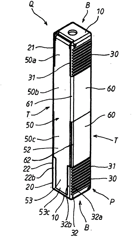
[0110] figure 1 Shown is Embodiment 1 of the tool container related to the present invention. The tool container is used for accommodating rod-shaped tools such as drill bits or end mills. The cross section of the tool container is square, and the longitudinal section of the tool container is rectangular. In addition, in the first embodiment, the overall length of the tool container is about 85 mm, and the cross-sectional size of the tool container is about 13 mm×13 mm.

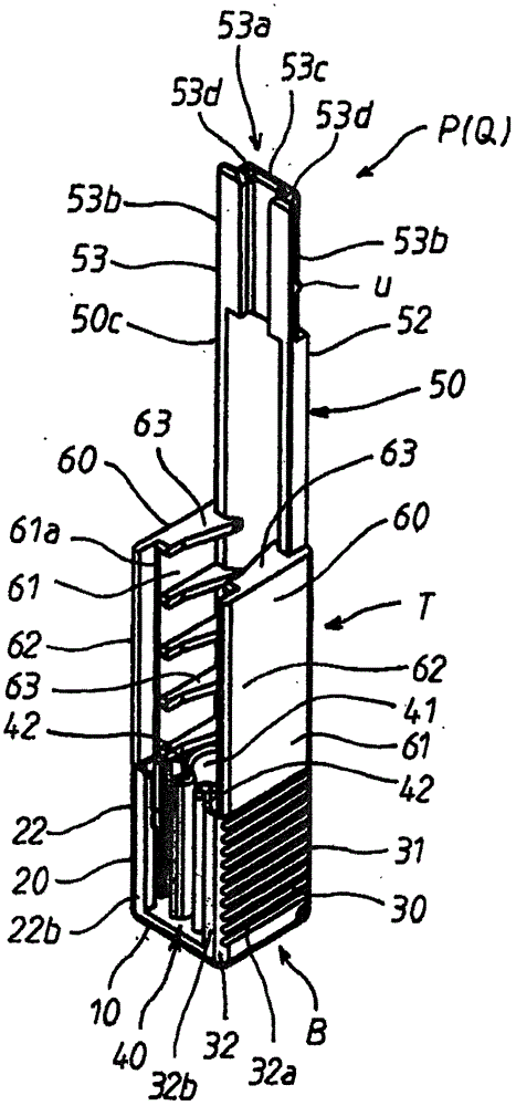
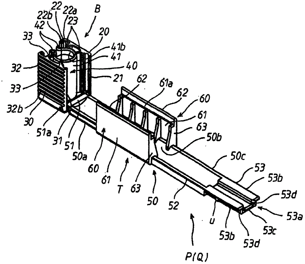
[0111] The tool container such as Figure 1 ~ Figure 4 Wherein shown in any figure, be provided with the two side container parts P, Q of elongated ruler shape.

[0112] These two side container parts P, Q are each as described later, are integrally formed and have the same structure, and these two side container parts P, Q are assembled with the mode that can disassemble each other and constitute this tool container (referring to figure 1 ).

[0113] One side container part P, such as Figure 1 to Figure ...

Embodiment 2

[0198] Figure 14 and Figure 15 Shown is the main part of the second embodiment of the tool container related to the present invention. In this second embodiment, in the two-side container parts P and Q described in the first embodiment, the bottom wall 10 of the container part B is respectively provided with a rear end 12 to replace the rear end 11, and the rear end 12 is in the On its rear end, at the respective lower rear end positions and Figure 14 The up and down directions of the icons are on the same straight line.

[0199] In addition, in the second embodiment, in the two-side container parts P and Q described in the first embodiment, the main plate 50 of the back plate material T is on the extended bottom end portion 51 of the base end plate portion 50a, through the narrow The rear end portion 12 of the bottom wall 10 of the container component B is integrally connected to the rear end portion 12 of the bottom wall 10 of the container part B so as to be rotatable...


PUM


Abstract

The present invention provides tool boxes, which enables bar-shaped tools not to be moved when the bar-shaped tools are accommodated, is designed elaborately, is equipped with two box parts without additional parts, and can be assembled by simply and mutually operating the two box parts with the same constructions. When the two side box parts P and Q that are molded integrally and have the same constructions, are assembled, a mainboard 50 of the box part P is clamped among the extending side parts of the two side slave plates 60 of the box part Q, the two edges of a cylinder 40, and the front side parts of the left and right two side walls 20, 30 of the box body B of the box part Q, via a front end side plate part 50c and a middle plate part 50b, at the same time, the mainboard 50 of the box part Q is clamped among the extending side parts of the two side slave plates 60 of the box part P, the two edges of the cylinder 40 of the box body B, and the front side parts of the left and right two side walls 20, 30 of the box body B of the box part P, via the front end side plate part 50c and the middle plate part 50b.

Description

technical field [0001] The present invention relates to a tool container suitable for accommodating rod-shaped tools such as drills and end mills. Background technique [0002] Conventionally, a tool case described in the following Patent Document 1 has been proposed as a tool container of this type. The tool box is provided with a lower shell with a square cross-section; an upper shell that can be embedded in the opening of the lower shell with a square cross-section; and a cushioning material disposed on the bellows structure at the bottom of the lower shell. . [0003] Therefore, when a rod-shaped tool is stored in the above-mentioned tool box, after the rod-shaped tool is inserted into the lower case from the front end toward the cushioning material, the elasticity of the cushioning material is adjusted from the opening end of the lower case. The stick-shaped tool exposed under the original state is surrounded, and the way of inserting the upper casing makes the stick-...

Claims


Application Information

Patent Timeline
Patent Type & Authority Patents(China)
IPC IPC(8): B65D85/20B65D81/05
CPCB23Q13/00B65D77/26B65D81/107B65D85/00
Inventor 陶山智靖老平智弘
Owner 伊特模禄株式会社
Learn More