

Steel plate-steel support combined lateral force resisting member and beam column structure applying same
A technology of beam-column structure and steel support, which is applied to building components, building structures, and earthquake resistance, can solve problems such as structural deformation capacity, weak energy dissipation capacity, reduced ductility, and loss of bearing capacity, and achieves excellent earthquake resistance. The effect of small steel consumption and improved energy consumption capacity
- Summary
- Abstract
- Description
- Claims
- Application Information
AI Technical Summary
Problems solved by technology
Method used
Image

Examples
Embodiment 1
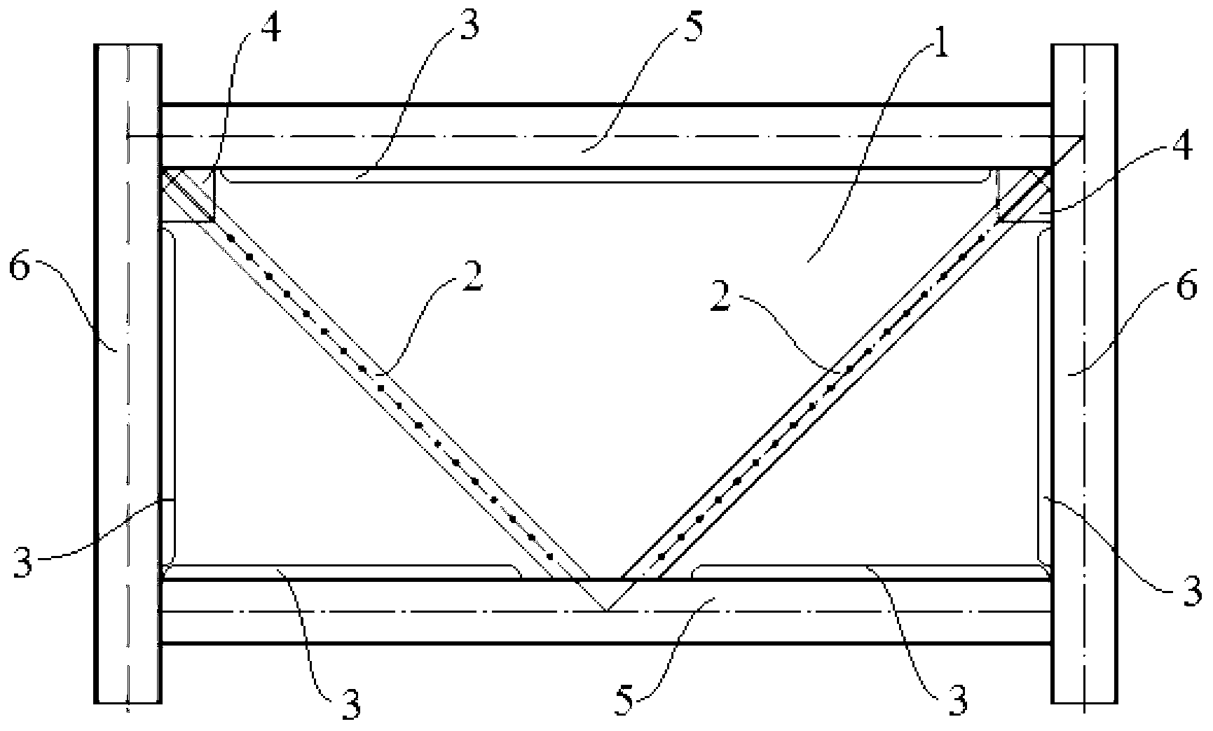
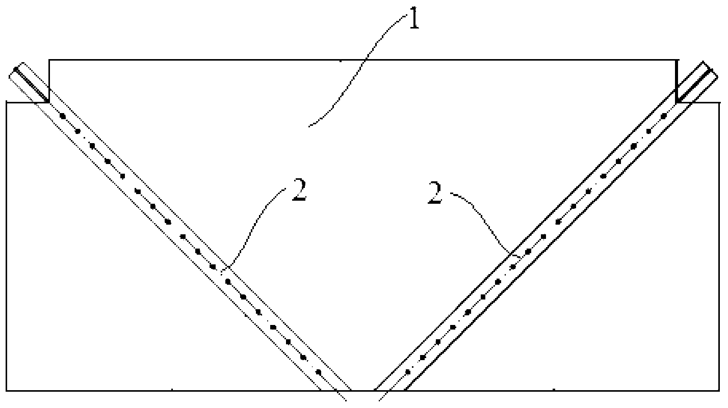
[0044] A steel plate-steel support combination anti-lateral force member in this embodiment includes a steel plate 1 and a steel support 2 integrated with the steel plate 1. The shape of the steel plate 1 is a rectangle with two corners on the same side removed, forming a " The shape of the cut part is square. The steel support 2 includes two symmetrical parts, which are respectively placed on both sides of the steel plate 1. The cross-sectional shape of the steel support 2 composed of the two parts is rectangular. The two parts of the steel support 2 Some are channel-section steel made by cold working. Ten bolt holes 8 are equidistantly opened on the steel support 2, and the distance between the bolt holes 8 and the end of the steel support 2 is 150mm, and ten bolt holes 8 are also opened on the corresponding position of the steel plate 1, and the two parts of the steel support 2 They are respectively connected to the steel plate 1 through high-strength bolts and nuts, and hi...
Embodiment 2
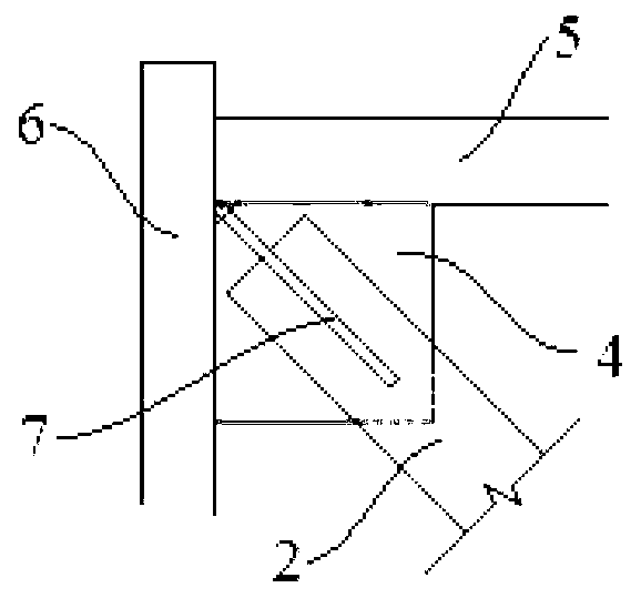
[0047] The basic structure of a steel plate-steel support composite anti-lateral force member and the beam-column structure using the member in this embodiment is the same as that of embodiment 1, except that the steel support 2 includes two symmetrical parts, which are respectively placed on the steel plates On both sides of 1, the cross-sectional shape of the steel support 2 composed of the two parts is circular. 1 bolt hole 8, the distance between the bolt hole 8 and the end of the steel support 2 is 175mm, and 15 bolt holes 8 are also provided at the corresponding position of the steel plate 1, the large diameter of the high-strength bolt and nut is 14mm, and the distance between the high-strength bolts is 250mm, The material of steel plate 1 and steel support 2 is Q345. The thickness of the fish plate 3 is 2.5 times the thickness of the steel plate 1, and a corner is cut off on the gusset plate 4 and the gusset plate stiffener 7, and the size of the cut corner is 30 mm. ...
Embodiment 3
[0049] The basic structure of a steel plate-steel support composite anti-lateral force member and the beam-column structure using the member of this embodiment is the same as that of embodiment 1, the difference is that 20 bolt holes 8 are equidistantly opened on the steel support 2 , the distance between the bolt holes 8 and the end of the steel support 2 is 200 mm, and there are 20 bolt holes 8 on the corresponding position of the steel plate 1. The material of support 2 is Q345. The thickness of the fish plate 3 is three times the thickness of the steel plate 1, and a corner is cut off on the gusset plate 4 and the gusset plate stiffener 7, and the size of the cut corner is 40 mm.
[0050] In order to better understand the content of the present invention, the manufacturing process of a steel plate-steel support composite lateral force resisting member and a beam-column structure using the member is given now.
[0051] To make a beam-column structure using a steel plate-st...
PUM
| Property | Measurement | Unit |
|---|---|---|
| Large diameter | aaaaa | aaaaa |
Abstract
Description
Claims
Application Information