Pressing cap structure of hydraulic jar

A technology of jar and cap structure, which is applied to wellbore/well components, earth-moving drilling, etc., can solve the problems of loosening and withdrawing of screw 3, straining and jarring cylinder, and short service life.

Inactive Publication Date: 2013-08-14
CHONGQING WANGJIANG IND
View PDF7 Cites 4 Cited by
  • Summary
  • Abstract
  • Description
  • Claims
  • Application Information

AI Technical Summary

Problems solved by technology

This hydraulic jar pressure cap structure, since the pressure cap 1 is fixedly connected with the mandrel 5 by tightening the screw 3 in the screw hole 1-1, after the hydraulic jar enters the well, the pressure cap 1 is due to the The vibration of the hydraulic jar and the shock of the hydraulic jar can easily cause the screw 3 to loosen and withdraw, strain the shock cylinder 4, and cause the hydraulic jar to fail, work invalid, and have a short life.
For this reason, it is necessary to frequently replace the shock cylinder 4 to ensure normal operation, which increases the cost of use

Method used


Image

  • Pressing cap structure of hydraulic jar
  • Pressing cap structure of hydraulic jar
  • Pressing cap structure of hydraulic jar

Examples


Embodiment Construction

[0027] Specific embodiments of the present invention will be described in detail below in conjunction with the accompanying drawings.

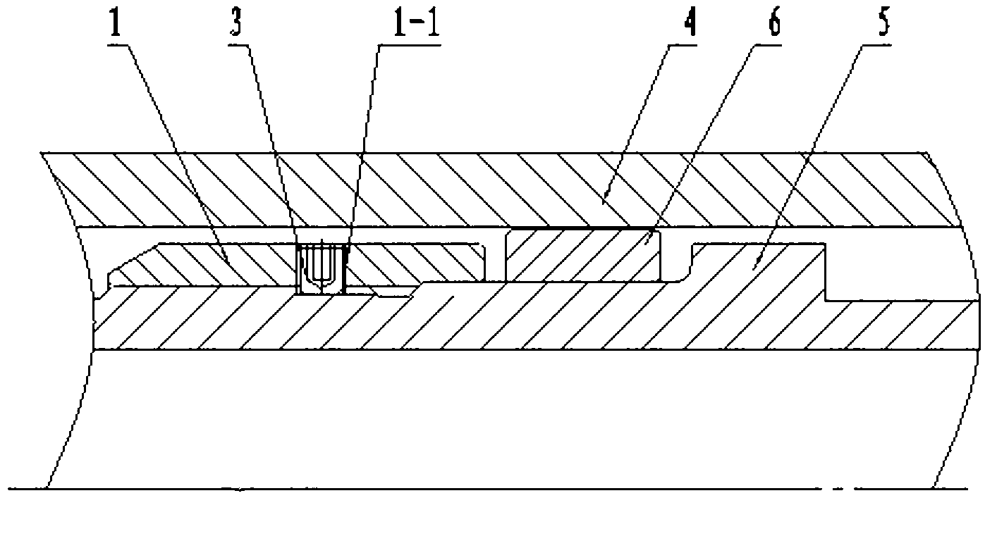
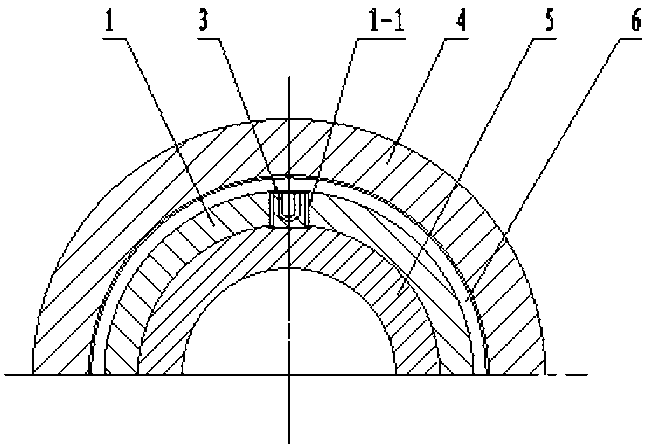
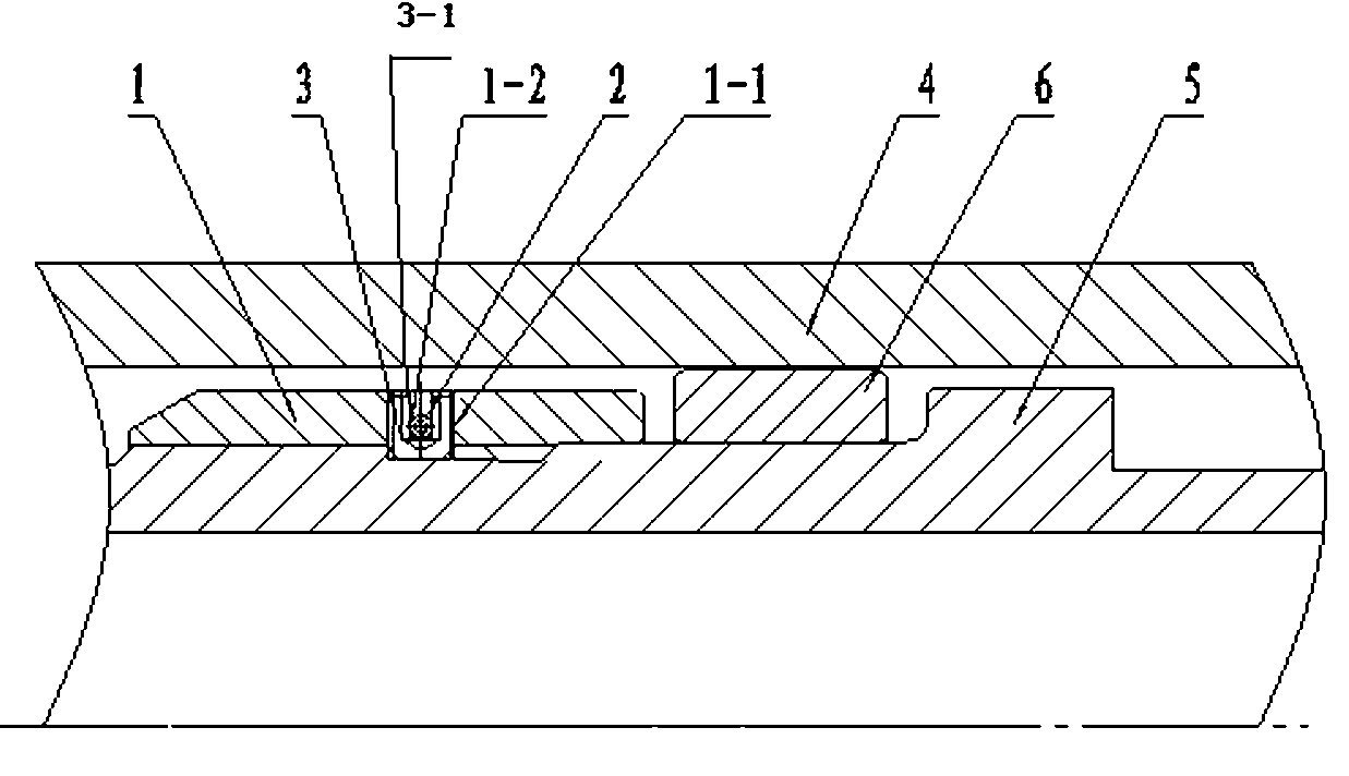
[0028] see image 3 , Figure 4 , Figure 5 , Image 6 , Figure 7 , Figure 8 and Figure 9 As shown, the pressure cap structure of the hydraulic jar of the present invention includes a pressure cap 1 for limiting the axial movement of the overflow piston 6, a shock cylinder 4 and a mandrel 5, and the pressure cap 1 is set in the shock fluid. On the mandrel 5 in the cylinder 4, the radial direction of the pressure cap 1 is provided with a screw hole 1-1, and the pressure cap 1 is fixedly connected with the mandrel 5 by tightening the screw 3 in the screw hole 1-1, and it is characterized in that: Including the connecting pin 2, a through hole 1-2 is opened on the pressure cap 1 perpendicular to the direction of the screw hole 1-1, and a groove 3-1 matched with the through hole 1-2 is opened on the screw 3. The connecting pin 2 passes t...


PUM


Abstract

The invention discloses a pressing cap structure of a hydraulic jar. The pressing cap structure of the hydraulic jar comprises a pressing cap (1) for limiting axial movement of an overflow piston (6), a jarring hydraulic cylinder (4) and a mandril (5). The pressing cap (1) is sleeved on the mandril (5) located in the jarring hydraulic cylinder (4), a screw hole (1-1) is arranged in the radial direction of the pressing cap (1), and a screw (3) in the screw hole (1-1) is tightened to enable the pressing cap (1) to be fixedly connected with the mandril (5). The pressing cap structure of the hydraulic jar is characterized by comprising a connection pin (2), a through hole (1-2) is arranged on the pressing cap (1) in the direction perpendicular to the screw hole (1-1), the screw (3) is provided with a groove (3-1) matched with the through hole (1-2), and the connection pin (2) penetrates through the through hole (1-2) to be fixedly connected with the groove (3-1). The pressing cap structure of the hydraulic jar has the advantages of being capable of avoiding loosening and long in service life.

Description

technical field [0001] The invention relates to a hydraulic jar, in particular to a hydraulic jar pressing cap structure. Background technique [0002] The pressure cap is the core part of the hydraulic jar in petroleum machinery products. Its main function is to limit the axial movement gap of the overflow piston, so as to ensure the jarring function of the hydraulic jar. At present, the structure of the pressure cap of the common hydraulic jar at home and abroad can be found in figure 1 As shown, it includes a pressure cap 1 for restricting the axial movement of the overflow piston 6, a shock cylinder 4 and a mandrel 5. The pressure cap 1 is set on the mandrel 5 located in the shock cylinder 4. The pressure cap 1 A screw hole 1-1 is provided in the radial direction, and the pressure cap 1 is fixedly connected with the mandrel 5 by tightening the screw 3 in the screw hole 1-1. This hydraulic jar pressure cap structure, since the pressure cap 1 is fixedly connected with th...

Claims


Application Information

Patent Timeline
Patent Type & Authority Applications(China)
IPC IPC(8): E21B31/113
Inventor 李道贵潘大东
Owner CHONGQING WANGJIANG IND
Why Eureka
Try Eureka