Double pipe for heat exchanger

A heat exchanger, double-layer tube technology, applied in heat exchange equipment, heat exchanger types, indirect heat exchangers, etc., can solve the problem of blockage of the outer flow path, flow path area, flow path fluidity deterioration, and flow path thermal efficiency. Reduce and other problems to achieve the effect of excellent heat exchange performance

Active Publication Date: 2013-08-14
FURUKAWA SKY ALUMINUM CORP
View PDF7 Cites 13 Cited by
  • Summary
  • Abstract
  • Description
  • Claims
  • Application Information

AI Technical Summary

Problems solved by technology

However, when the double-layer pipe with such a structure is applied to, for example, an automobile air conditioner and the like and is bent, the shape of the convex portion of the inner pipe is greatly deformed, and adjacent convex portions contact or approach each other, resulting in a part of the If the outer channel is clogged or the area of ​​the channel is narrowed, the fluidity of the channel will deteriorate, resulting in an increase in pressure loss and a decrease in the thermal efficiency of the channel.

Method used


Image

  • Double pipe for heat exchanger
  • Double pipe for heat exchanger
  • Double pipe for heat exchanger

Examples


Embodiment 1)

[0069] Regarding the double-layer pipe for heat exchanger of the present invention, use Figure 1 to Figure 4 Be explained.

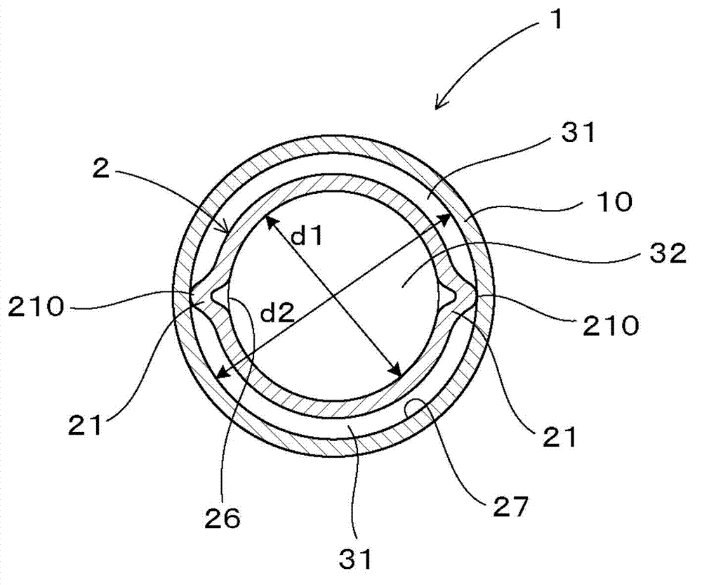
[0070] Such as image 3 As shown, the double-layer tube 1 of the present embodiment is a double-layer tube for a heat exchanger, and has a double-layer tube structure in which an inner tube 2 is arranged inside an outer tube 10, and is used to communicate with the fluid flowing inside the inner tube 2. Heat exchange between the fluid flowing between the inner tube 2 and the outer tube 10 .

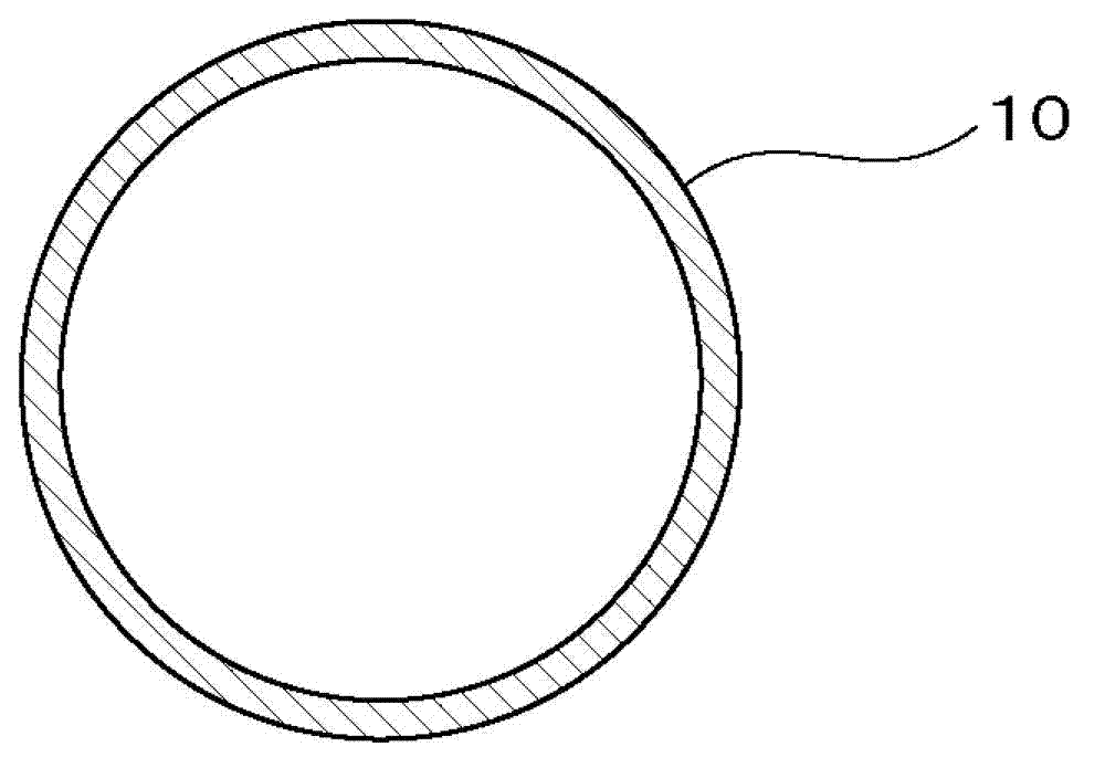
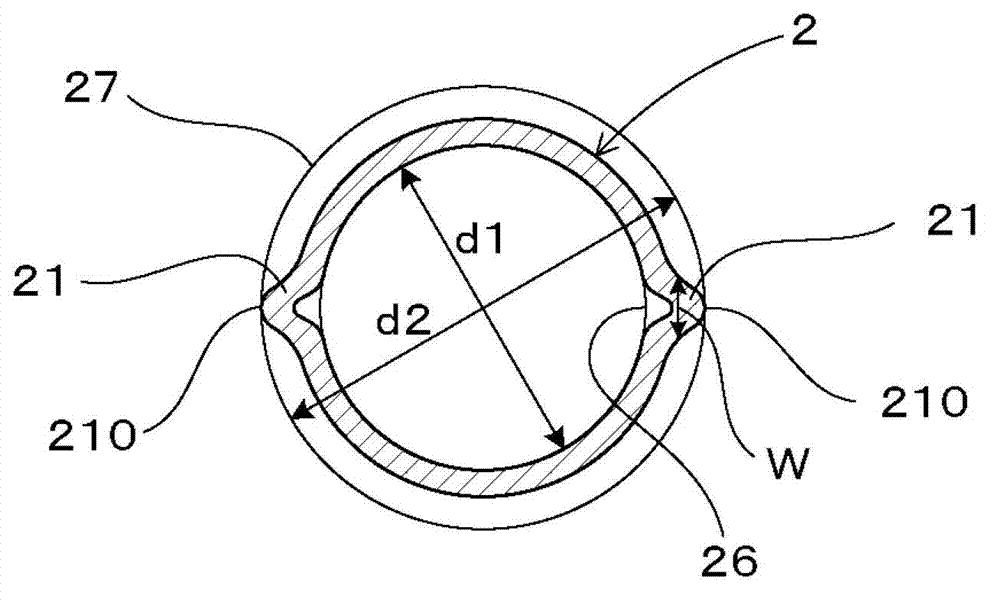
[0071] Such as figure 2 , Figure 4 As shown, the cross-sectional shape of the inner tube 2 has a shape having two protrusions 21 formed by deforming a part of the circumference of a circle so as to protrude outward of the circle. Furthermore, it has a shape in which the position of the convex part 21 is displaced helically in the longitudinal direction. The outer tube 10 has a smooth tube shape with a circular cross-sectional shape. And, if image 3 As show...

Embodiment 2)

[0086] Such as Figure 5 As shown, the cross-sectional shape of the inner tube 2 of the double-layered tube 102 of this embodiment has four protrusions 21 formed by deforming a part of the circumference of a circle so as to protrude outward of the circle at equal intervals. Therefore, if Figure 5 As shown, between the outer tube 10 and the inner tube 2, outer flow paths 31 divided into four positions in the circumferential direction at equal intervals are formed. In addition, in this embodiment, the width dimension W perpendicular to the radial direction of all the protrusions 21 becomes smaller toward the outer peripheral side. In addition, the double-layered pipe 1 of the present embodiment uses the raw material for the outer pipe with an outer diameter of φ21 mm and a wall thickness of 1.2 mm made of the material A3003, and an inner pipe material with an outer diameter of φ19 mm and a wall thickness of 1.2 mm made of the material A3003. Other than that, it produced subst...

Embodiment 3)

[0091] Such as Figure 6 As shown, the cross-sectional shape of the inner tube 2 of the double-layered tube 103 of this embodiment has eight protrusions 21 formed by deforming a part of the circumference of a circle so as to protrude to the outside of the circle at equal intervals. Therefore, if Figure 6 As shown, between the outer tube 10 and the inner tube 2, outer flow paths 31 divided into eight positions in the circumferential direction at equal intervals are formed. In addition, in this embodiment, the width dimension W perpendicular to the radial direction of all the protrusions 21 becomes smaller toward the outer peripheral side. In addition, the double-layered pipe 103 of this embodiment uses the material A3003 with an outer diameter of 23 mm and a wall thickness of 1.3 mm for the outer pipe, and the material A3003 with an outer diameter of 21 mm and a wall thickness of 1.2 mm for the inner pipe. Other than that, it produced substantially in the same manner as in E...


PUM


Abstract

A double pipe for a heat exchanger includes an inner pipe having a plurality of spiral projections extending radially outward from an outer peripheral surface of the inner pipe. An outer pipe is disposed around the inner pipe. At least an inner peripheral surface of the outer pipe is at least substantially smooth and has an at least substantially circular cross section. The inner peripheral surface of the outer pipe contacts all of the projections of the inner pipe so as to define a plurality of peripherally-separated, outer flow paths between the inner pipe and the outer pipe. Fluid flowing within an inner flow path defined by the inner pipe exchanges heat with fluid flowing through the outer flow paths. Furthermore, an inscribed circle of the inner pipe has a first diameter (d1), an inscribed circle of the outer pipe has a second diameter (d2), and 0.6<d1 / d2.

Description

technical field [0001] The present invention relates to a double-layer tube for a heat exchanger that can be applied to, for example, a heat exchange cycle of an air conditioner for an automobile. Background technique [0002] A heat exchange cycle (also called a refrigeration cycle) of an automobile air conditioner, etc. is a system that includes a condenser, an evaporator, a compressor, and an expansion valve, and uses fluorocarbons, CO 2 Refrigerants such as ammonia and ammonia circulate in the circulation path connecting the above-mentioned components. In the above-mentioned heat exchange cycle, a structure is proposed in which double-layer pipes are arranged in the circulation path, and the high-temperature refrigerant discharged from the condenser and the low-temperature refrigerant discharged from the evaporator are separated in the double-layer space constituted by the double-layer pipes. The refrigerant convects and exchanges heat, thereby improving heat exchange p...

Claims


Application Information

Patent Timeline
Patent Type & Authority Applications(China)
IPC IPC(8): F28F1/10
CPCF28D7/026F28D2021/008F28D7/106F28D7/10F28D2021/0068F28F1/06
Inventor 松田真一加藤胜也
Owner FURUKAWA SKY ALUMINUM CORP
Why Eureka
Try Eureka