Photographing lens system

一种镜片系统、透镜的技术,应用在光学、仪器、光学元件等方向,能够解决影响成像品质、像差补正困难等问题,达到修正像差、光学总长度短、加强屈折力配置的效果

Active Publication Date: 2013-08-14
LARGAN PRECISION
View PDF6 Cites 2 Cited by
  • Summary
  • Abstract
  • Description
  • Claims
  • Application Information

AI Technical Summary

Problems solved by technology

U.S. Patent No. 7,564,635 discloses a camera lens with three lenses, but the three lenses are all positive refractive lenses, which makes it difficult to correct aberrations (such as chromatic aberration, etc.) in the system and affects image quality

Method used


Image

  • Photographing lens system
  • Photographing lens system
  • Photographing lens system

Examples


no. 1 example

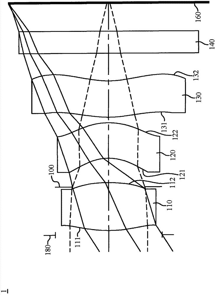
[0108] Please refer to Figure 1A to Figure 1D As shown, the photographic lens system 1 of the first embodiment is along the optical axis, from the object side to the image side (that is, along the Figure 1A from the left side to the right side) sequentially includes a diaphragm 180, a first lens 110, an aperture 100, a second lens 120, a third lens 130, an infrared filter filter 140 and an imaging surface 160 .

[0109] In this embodiment, the first lens 110 is made of plastic material and has positive refractive power, the object side 111 is convex, the image side 112 is convex, and both the object side 111 and the image side 112 are aspherical; the second lens 120 is plastic material and has negative refractive power, the object side 121 is concave, the image side 122 is convex, and both the object side 121 and the image side 122 are aspherical; the third lens 130 is made of plastic material and has negative refractive power, and the object side 131 is convex , the image ...

no. 2 example

[0123] Please refer to Figure 2A to Figure 2D As shown, the second embodiment sequentially includes a first lens 210 , an aperture 200 , a second lens 220 , a third lens 230 , an infrared filter 240 and an imaging surface 260 .

[0124] In the second embodiment, a protective glass 250 is inserted between the infrared filter 240 and the imaging surface 260, which does not affect the focal length of the photographic lens system 2; appendix.

[0125] The first lens 210 is made of plastic material and has positive refractive power, the object side 211 is convex, the image side 212 is convex, and both the object side 211 and the image side 212 are aspherical; the second lens 220 is made of plastic and has negative refractive power , the object side 221 is concave, the image side 222 is convex, and both the object side 221 and the image side 222 are aspherical; the third lens 230 is made of plastic material and has negative refractive power, the object side 231 is convex, and the ...

no. 3 example

[0136] Please refer to Figure 3A to Figure 3D As shown, the third embodiment sequentially includes a first lens 310 , an aperture 300 , a second lens 320 , a third lens 330 , an infrared filter 340 and an imaging surface 360 ​​.

[0137] The first lens 310 is made of plastic material and has positive refractive power, the object side 311 is convex, the image side 312 is convex, and both the object side 311 and the image side 312 are aspheric; the second lens 320 is made of plastic and has negative refractive power , the object side 321 is concave, the image side 322 is convex, and both the object side 321 and the image side 322 are aspheric; the third lens 330 is made of plastic material and has negative refractive power, the object side 331 is convex, and the image side 332 is concave , and both the object side 331 and the image side 332 are aspherical.

[0138] The detailed data of the photographic lens system 3 is shown in Table 3-1 below:

[0139] Table 3-1

[0140] ...


PUM


Abstract

The utility model discloses a photographic lens system. The photographic lens system comprises a first lens with positive refracting power, a second lens with negative refracting power and a third lens with the negative refracting power along the object side to the image side of an optical axis in sequence, wherein both the object side surface and the image side surface of the first lens are convex surfaces and non-spherical surfaces. Through the first lens with double convex surfaces, the configuration of the refracting power of the first lens can be reinforced effectively, the optical total length of the photographic lens system can be shortened, the spherical aberration can be modified and high imaging quality can be achieved.

Description

technical field [0001] The invention relates to a photographic lens system, in particular to a photographic lens system composed of compound lenses. Background technique [0002] In recent years, with the rise of portable electronic products with photography functions, the demand for miniature imaging modules has increased day by day, and the photosensitive elements of general photography lenses are nothing more than Charge Coupled Devices (CCD) or complementary There are two types of metal oxide semiconductor elements (Complementary Metal-Oxide Semiconductor Sensor, CMOS Sensor), and with the improvement of semiconductor process technology, the pixel size of the photosensitive element is reduced. How to improve the imaging quality of the miniaturized photographic lens under effective space conditions become the focus of industry attention. [0003] Existing miniaturized camera lenses, in order to reduce manufacturing costs, mostly adopt a two-piece lens structure, such as ...

Claims


Application Information

Patent Timeline
Patent Type & Authority Applications(China)
IPC IPC(8): G02B13/00G02B13/18G02B13/22G02B13/06G02B1/04G02B1/00
CPCG02B13/18G02B1/04G02B1/00G02B13/0035G02B13/06G02B13/00G02B13/22
Inventor 蔡宗翰陈纬彧
Owner LARGAN PRECISION
Why Eureka
Try Eureka