
Touch panel and touch display device

A touch panel and substrate technology, applied in the direction of instruments, electrical digital data processing, data processing input/output process, etc., can solve the problems of total impedance increase, signal transmission delay, slow charge and discharge speed, etc., to achieve touch control good effect

Inactive Publication Date: 2013-08-14
DONGGUAN MASSTOP LIQUID CRYSTAL DISPLAY +1
View PDF5 Cites 27 Cited by
  • Summary
  • Abstract
  • Description
  • Claims
  • Application Information

AI Technical Summary

Problems solved by technology

However, because the distance between the first sensing pad of the first electrode series and the connected first sensing pad is relatively long, the elongated bridge pattern needs to be elongated, which also leads to an increase in the total impedance of the entire electrode series. High, resulting in signal transmission delay, slow charging and discharging speed

Method used


Image

  • Touch panel and touch display device
  • Touch panel and touch display device
  • Touch panel and touch display device

Examples


Embodiment Construction

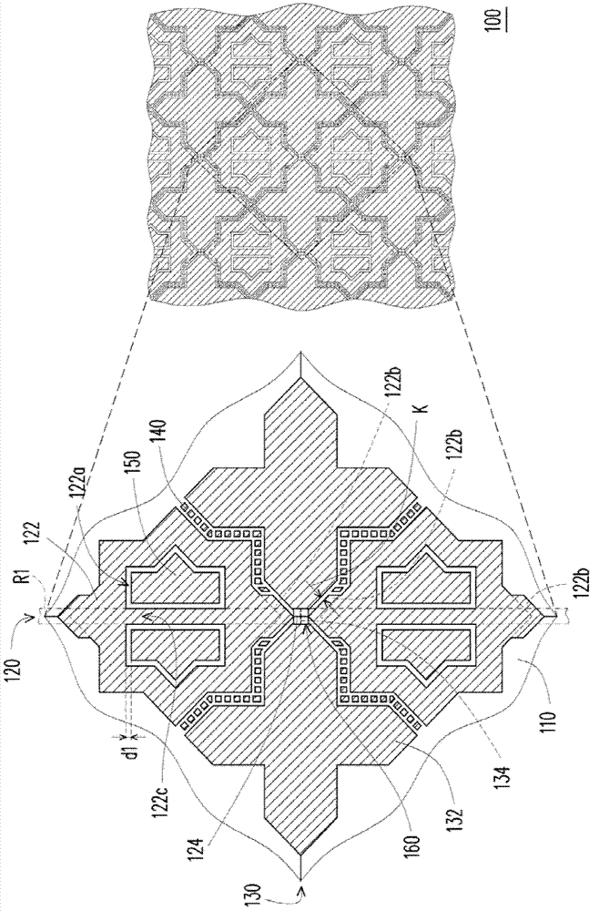
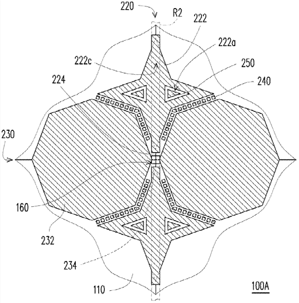
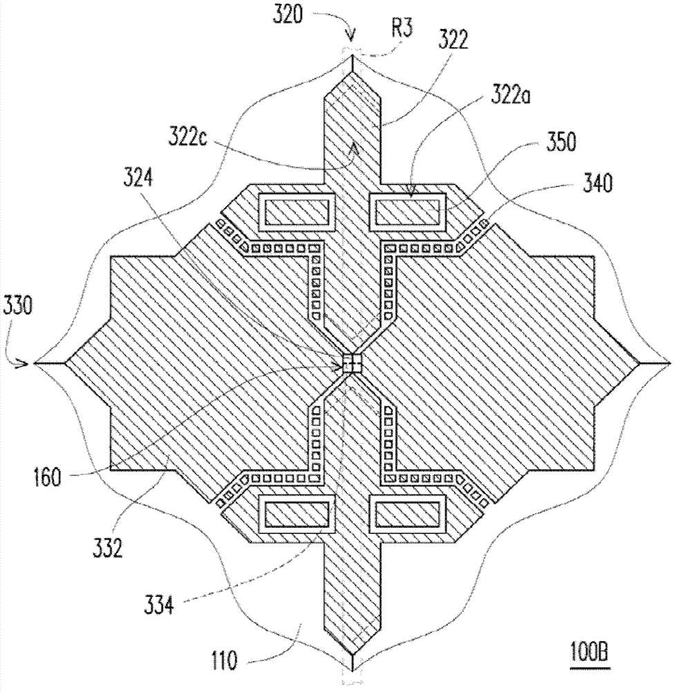
[0011] Please refer to figure 1 The touch panel 100 of this embodiment includes a substrate 110, a plurality of first electrode series 120 electrically insulated from each other, a plurality of second electrode series 130 electrically insulated from each other, and a plurality of electrodes located between the first electrode series 120 and the second electrode series 130. A plurality of first floating patterns 140 between the two electrode series 130 .

[0012] The first electrode series 120, the second electrode series 130 and the first floating pattern 140 can be disposed on the same side of the substrate 110, and the first floating pattern 140 can compensate the first electrode series 120 and the second electrode series The optical visual effect problem caused by the gap between 130 can further improve the uniformity of visual effect of the touch panel 100 .

[0013] Each first electrode series 120 includes a plurality of first sensing pads 122 and a plurality of first br...


PUM

PropertyMeasurementUnit
Widthaaaaaaaaaa

Abstract

The invention provides a touch panel and a touch display device. The touch panel comprises a plurality of first and second electrode arrays which are located on a substrate and mutually electrically insulated. Each first electrode array comprises a plurality of first sensing pads and a plurality of first bridging patterns. The second electrode arrays located on the substrate and mutually electrically insulated are staggered with the first electrode arrays. Each second electrode array comprises a plurality of second sensing pads and a plurality of second bridging patterns. A plurality of first floating patterns are arranged between the first electrode arrays and the second electrode arrays. Each first sensing pad is provided with at least one extension part. No first floating pattern is arranged between each extension part and the second electrode array adjacent to the same.

Description

technical field [0001] The present invention relates to an electronic device, in particular to a touch panel and a touch display device. Background technique [0002] A conventional capacitive touch panel includes a plurality of first electrode series electrically insulated from each other and a plurality of second electrode series electrically insulated from each other. The first electrode series and the second electrode series are alternately arranged and electrically insulated. A plurality of floating electrodes are arranged at gaps between the first electrode series and the second electrode series. [0003] Through the design of the floating electrodes, the width of the gap is reduced, so that the user is not easy to perceive the outline of the first electrode series (or the second electrode series). However, because the distance between the first sensing pad of the first electrode series and the connected first sensing pad is relatively long, the elongated bridge patt...

Claims


Application Information

Patent Timeline
IPC IPC(8): G06F3/044
Inventor 周仁彦叶政谚周建良林仲凯邓志容苏振豪
Owner DONGGUAN MASSTOP LIQUID CRYSTAL DISPLAY
Learn More