
Mutual-capacitance touch display panel and touch detection method thereof

A technology for a touch display panel and a detection method, which is applied to the input/output process of electrical digital data processing, instruments, and data processing, etc., can solve the problems affecting the touch effect and display quality of the display panel, easy mutual interference, and touch failure. and other problems, to achieve good touch effect, improve sensitivity and touch aging, and avoid interference.

Active Publication Date: 2015-07-22
TCL CHINA STAR OPTOELECTRONICS TECH CO LTD
View PDF4 Cites 2 Cited by
  • Summary
  • Abstract
  • Description
  • Claims
  • Application Information

AI Technical Summary

Problems solved by technology

In the display panel using the above technology, the touch driving signal is usually a time-domain driving signal, that is, the change of the driving signal at different times is analyzed to analyze the touch position. However, in the scanning process of the same display frame, adjacent touch lines The transmitted driving signals are likely to interfere with each other, resulting in phenomena such as ghosts and touch failures, thereby affecting the touch effect and display quality of the display panel

Method used


Image

  • Mutual-capacitance touch display panel and touch detection method thereof
  • Mutual-capacitance touch display panel and touch detection method thereof

Examples


Embodiment Construction

[0017] The technical solutions in the embodiments of the present invention will be clearly and completely described below in conjunction with the accompanying drawings in the embodiments of the present invention. Obviously, the embodiments described below are only part of the embodiments of the present invention, not all of them. Example. Based on the embodiments of the present invention, all other embodiments obtained by persons of ordinary skill in the art without creative efforts fall within the protection scope of the present invention.

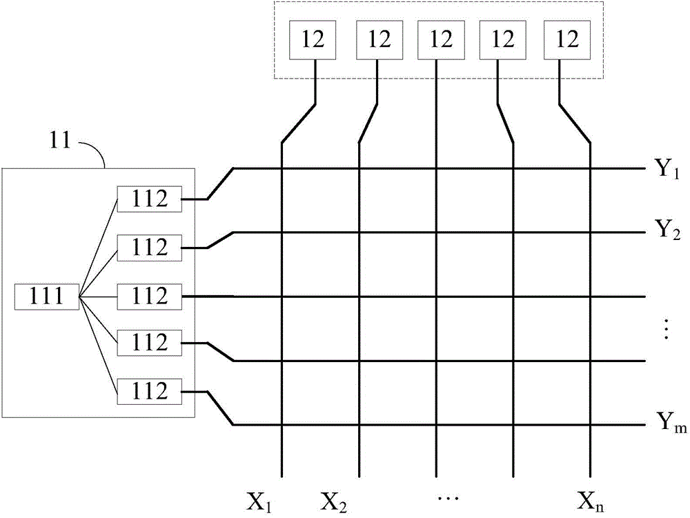
[0018] figure 1 It is a structural schematic diagram of an embodiment of the mutual capacitance touch display panel of the present invention. Such as figure 1 As shown, the mutual capacitive touch display panel includes a plurality of drive electrodes Y arranged at intervals along the first direction 1 ,Y 2 ,...,Y m , a plurality of sensing electrodes X arranged at intervals along the second direction 1 ,X 2 ,...,X n , and with a ...


PUM


Abstract

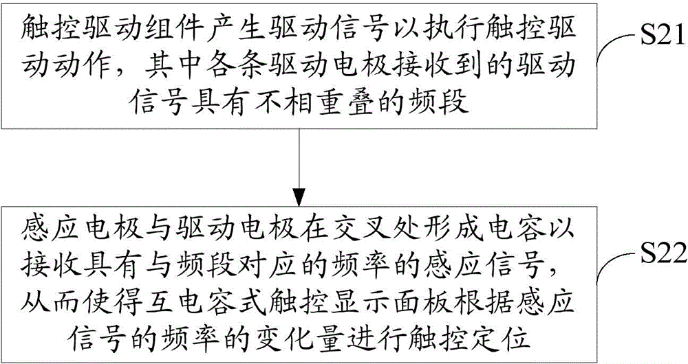
The invention discloses a mutual-capacitance touch display panel and a touch detection method thereof. The touch detection method comprises the steps that a touch drive component generates drive signals to perform touch drive action, wherein the drive signals received by all drive electrodes have non-overlapping frequency bands; induction electrodes and the drive electrodes form capacitors at the cross positions to receive induction signals with the frequency corresponding to the frequency bands, and therefore the mutual-capacitance touch display panel can perform touch positioning according to the variable quantity of the frequency of the induction signals. According to the mutual-capacitance touch display panel and the touch detection method thereof, mutual interference among the drive signals received by all the drive electrodes can be avoided, the phenomena such as ghost points and touch failure are prevented from generating, and the touch effect is good.

Description

technical field [0001] The present invention relates to the technical field of liquid crystal panels, in particular to the technical field of touch detection, and in particular to a mutual capacitance touch display panel and a touch detection method thereof. Background technique [0002] Currently, display panels with integrated touch and display functions are becoming more and more popular. They have the advantages of high sensitivity, fast response time and multi-touch. Common mutual capacitance touch display panels use OGS (One Glass Solution, single-chip Touch) technology, On-cell technology that embeds capacitive touch function between color filter substrate and polarizer, and In-cell technology that embeds capacitive touch function into pixels. In the display panel using the above technology, the touch driving signal is usually a time-domain driving signal, that is, the change of the driving signal at different times is analyzed to analyze the touch position. However, ...

Claims


Application Information

Patent Timeline
Patent Type & Authority Applications(China)
IPC IPC(8): G06F3/044
Inventor 徐向阳
Owner TCL CHINA STAR OPTOELECTRONICS TECH CO LTD
Learn More