
A Broadband Periodic Absorbing Structure of Single-Layer Composite Units

A wave structure and broadband technology, applied in the field of electromagnetic wave absorbing structure, can solve the problems of occupied space, limited working bandwidth, thick thickness, etc.

Inactive Publication Date: 2016-07-06
UNIV OF ELECTRONICS SCI & TECH OF CHINA
View PDF4 Cites 0 Cited by
  • Summary
  • Abstract
  • Description
  • Claims
  • Application Information

AI Technical Summary

Problems solved by technology

However, these absorbers have a common disadvantage: although the effect of resonance superimposed broadband absorption can be achieved by increasing the thickness and the resonance frequency point, the working bandwidth is limited by the thickness, and the result of broadband absorption is that the thickness is very large ,take up space
However, these patterns are limited by their own characteristics. There is only one absorption peak in the low frequency band (thickness less than a quarter of the frequency band), and it is difficult to achieve the absorption effect of the low frequency band.

Method used


Image

  • A Broadband Periodic Absorbing Structure of Single-Layer Composite Units
  • A Broadband Periodic Absorbing Structure of Single-Layer Composite Units
  • A Broadband Periodic Absorbing Structure of Single-Layer Composite Units

Examples


Embodiment 1

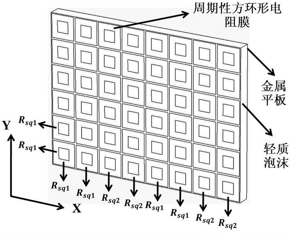
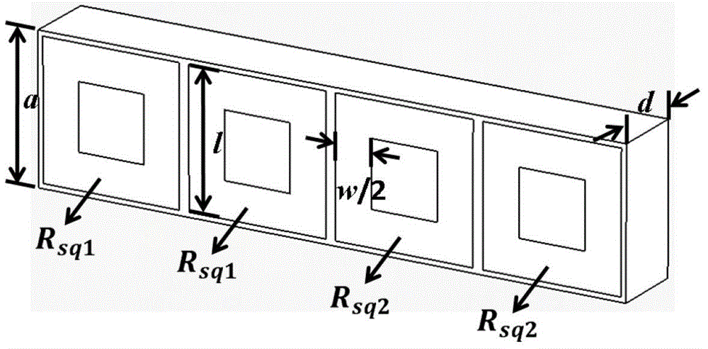
[0018] A single-layer composite unit broadband periodic absorbing structure, its specific size parameters are (in mm):

[0019] a=15, l=14, w=6.5-7.6, d=7.5, Rsq1=56Ω / □, Rsq2=190Ω / □.

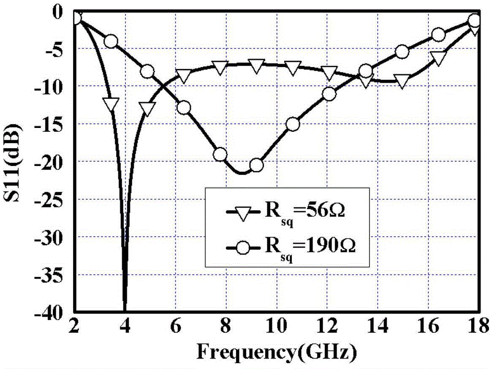
[0020] In the case of vertically incident TE or TM waves, when w=7.3, it has the absorbing performance as shown in the figure. The frequency band of 3-15GHz has a reflection coefficient below -5dB, and the frequency band of 3.5-14GHz has a reflection coefficient of below -10dB.

Embodiment 2

[0022] A single-layer composite unit broadband periodic absorbing structure, its specific size parameters are (in mm):

[0023] a=15, l=14, w=7.3, d=6.8-7.5, Rsq1=56Ω / □, Rsq2=190Ω / □.

[0024] In the case of vertically incident TE or TM waves, the entire frequency range from 3.5 to 16 GHz has a reflection coefficient below -5 dB, and 4 to 14 GHz has a reflection coefficient below -10 dB.

Embodiment 3

[0026] A single-layer composite unit broadband periodic absorbing structure, its specific size parameters are (in mm):

[0027] a=15, l=14, w=7.3, d=7.5, Rsq1=50-65Ω / □, Rsq2=190Ω / □.

[0028] In the case of vertically incident TE or TM waves, the entire frequency range from 3 to 16.5 GHz has a reflection coefficient below -5 dB, and 3.5 to 13.8 GHz has a reflection coefficient below -10 dB.


PUM


Abstract

The invention relates to a single-layer composite unit broadband periodic wave-absorbing structure, which belongs to the technical field of electronic materials. In the present invention, a dielectric layer with a periodic array resistance pattern printed on the metal plate is provided, the dielectric layer is composed of a foam layer and a periodic square-ring resistance film arranged on the foam layer, and the periodic array resistance film is composed of different resistance films. Composed of two resistive films.

Description

technical field [0001] The invention belongs to the technical field of electronic materials, in particular to an electromagnetic wave absorbing structure. Background technique [0002] During World War II, the widespread use of radar as an advanced long-distance detection tool gave birth to the emergence of radar stealth technology. In modern warfare, the electromagnetic environment is becoming more and more complex, and radar absorbing materials, as an effective means to improve the stealth penetration capability of weapons and equipment, have also received more and more attention from various military powers. In addition, with the widespread use of technical products such as mobile phones and microwave ovens that use electromagnetic waves as a medium in various fields of real life, the accompanying electromagnetic pollution such as electromagnetic radiation also poses a threat to human survival and health. Therefore, radar absorbing materials are also widely used in civil...

Claims


Application Information

Patent Timeline
Patent Type & Authority Patents(China)
IPC IPC(8): H05K9/00
Inventor 周佩珩张国瑞张辉彬张林博邓龙江谢建良陈良
Owner UNIV OF ELECTRONICS SCI & TECH OF CHINA
Learn More