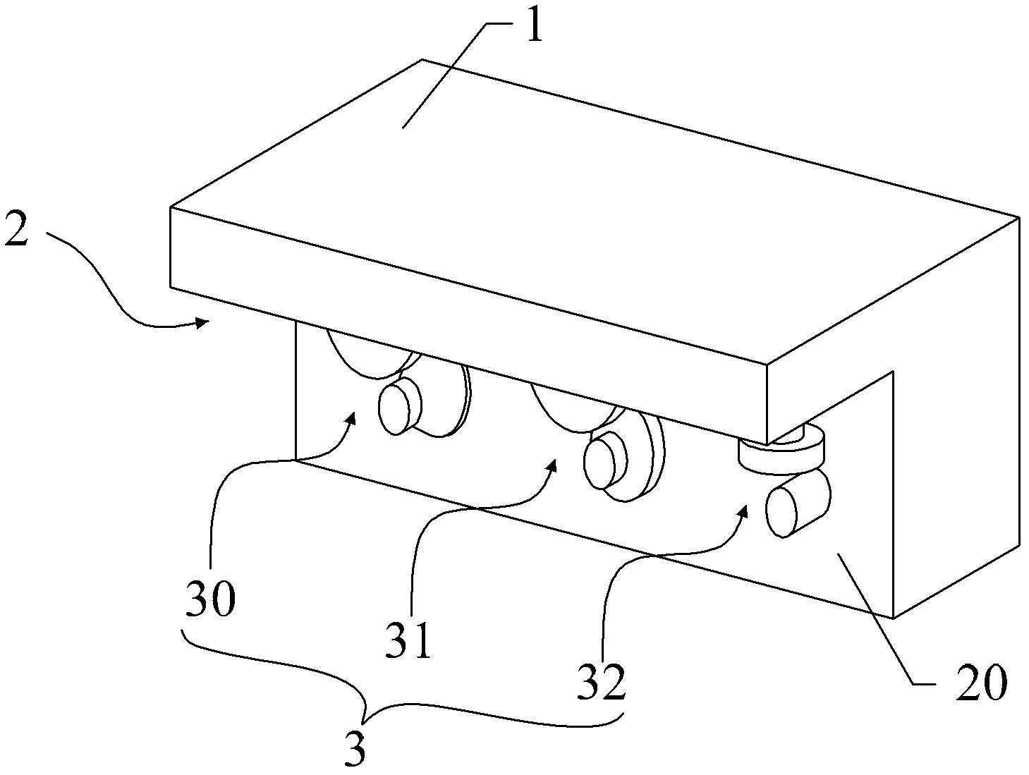
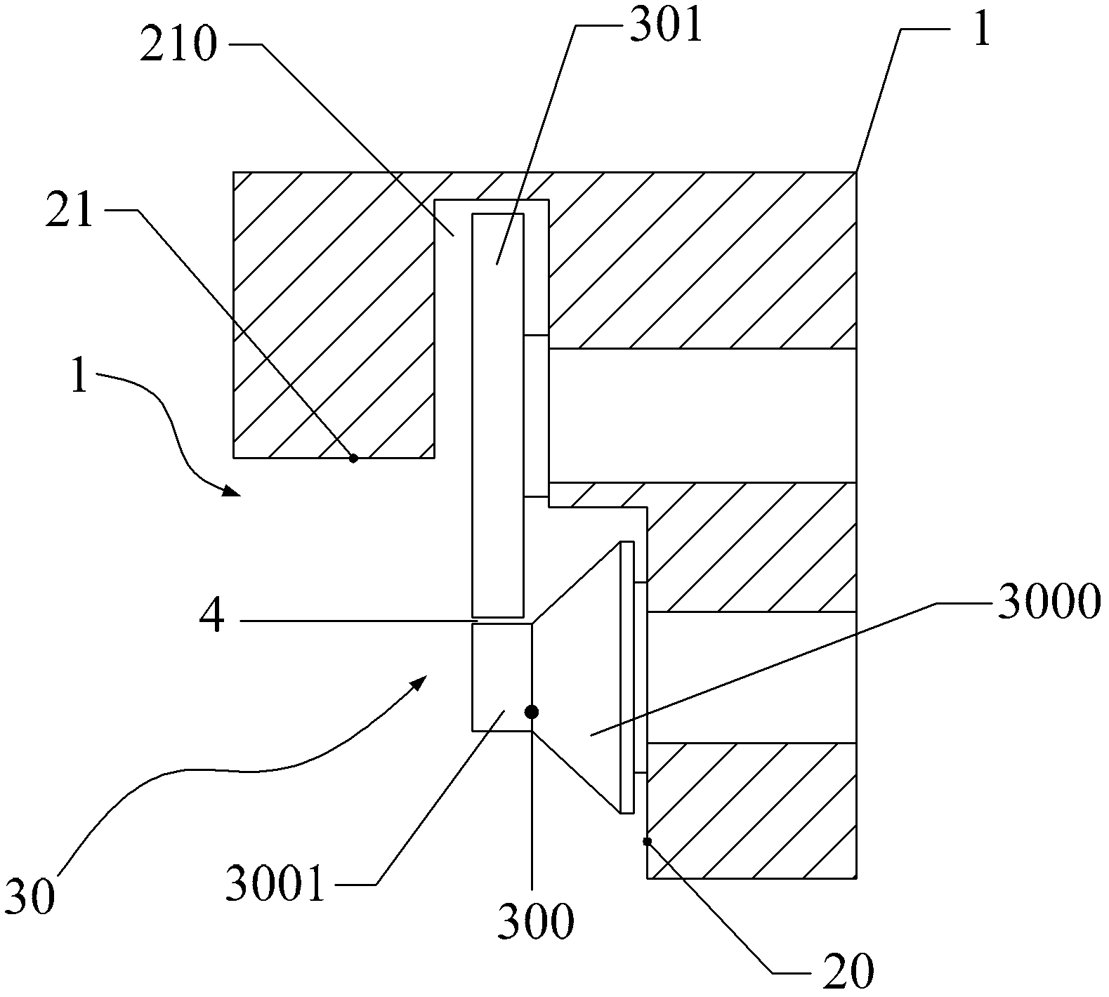
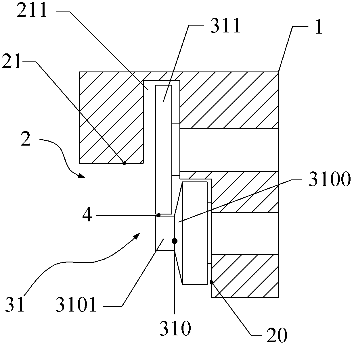
Trimming machine

A hemming machine and hemming technology, which is applied in the field of pressure processing, can solve problems such as gaps at the hemming, insufficient sealing, and reduced energy recovery effect of plate heat exchangers, so as to improve efficiency and avoid poor sealing effect

Active Publication Date: 2013-08-21
北京环都拓普空调有限公司
View PDF9 Cites 14 Cited by
  • Summary
  • Abstract
  • Description
  • Claims
  • Application Information

AI Technical Summary

Problems solved by technology

[0003] In the prior art, the seal between the heat exchange fins is manually folded and sealed by the staff, but the efficiency is low when the staff seals m

Method used


Image

  • Trimming machine
  • Trimming machine
  • Trimming machine

Examples


Embodiment 2

[0042] After the stacked heat exchanging fins are hemmed by the second hemming gear train 31, the edge of the lower heat exchanging fin 5b is 80-90 degrees. In practical applications, this angle may deviate; when the angle is less than When passing through the horizontal runner 320 of the third hemming wheel train 32 at 80 degrees to 90 degrees, the lower heat exchange fin 5b may be stuck on the third hemming gear train 32 because the bending angle is too large.

[0043] Therefore, preferably, as Figure 9 As shown, one end of the horizontal rotating wheel 320 close to the first rotating rod 321 is in the shape of a frustum of a cone. And, preferably, as Figure 10 As shown, the hemming mechanism 3 also includes a hemming wheel train 33;

[0044] The hemming wheel system 33 is composed of a corresponding second rotating rod 331 and a hemming wheel 330; the second rotating rod 331 is rotatably connected to the side wall 20 of the hemming groove 2; the hemming wheel is housed in...

Embodiment 3

[0048] For the hemming machine described in Embodiment 1 and Embodiment 2, when hemming the stacked heat exchange fins, the stacked heat exchange fins are driven to move to the fixed hemming machine by equipment such as a motor, and the hemming machine passes through the hemming machine Hemming groove 2 carries out hemming. When performing hemming, the stacked heat exchange fins need to be aligned with the hemming channel 4 , but when the stacked heat exchange fins deviate from the hemming channel, the hemming cannot be completed.

[0049] Therefore, preferably, as Figure 13 As shown, a limiting channel 8 is provided at one end of the housing 1 and outside the first hemming wheel train 30 , and the limiting channel 8 corresponds to the hemming channel 4 . Moreover, further, the longitudinal section of the limiting channel 8 is conical, and the tip of the cone is close to the side of the first hemming wheel train 30 .

[0050] Through the limiting channel 8 arranged outside ...


PUM


Abstract

The invention provides a trimming machine and belongs to the field of press working. The trimming machine is designed to solve the problem in the prior art that edge folding efficiency is low and a sealing effect of a flange is poor by means of manual edge folding. The trimming machine comprises a casing. A trimming groove is arranged on one side of the casing, at least one trimming mechanism is arranged in the horizontal direction in the trimming groove, and a trimming mechanism is formed by a first trimming wheel train, a second trimming wheel train and a third trimming wheel train which are arranged at intervals sequentially. Trimming channels are arranged at corresponding positions of a first upper press wheel and a first rolling portion, of a second upper press wheel and a second rolling portion and of a horizontal rotating wheel and a first rotating rod at intervals.

Description

technical field [0001] The invention relates to the field of pressure processing, in particular to a hemming machine. Background technique [0002] In air conditioning and ventilation systems, air-to-air energy recovery is achieved through energy recovery cores, which transfer the energy contained in the outgoing air to the incoming air. The commonly used air-to-air energy recovery core can be a plate heat exchanger, and the plate heat exchanger is formed by stacking several heat exchange fins. [0003] In the prior art, the seal between the heat exchange fins is manually folded and sealed by the staff, but the efficiency is low when the staff seals manually, and the seal is not firm enough, and there is a gap at the folded edge, thereby reducing the The effect of energy recovery in the plate heat exchanger. Contents of the invention [0004] Embodiments of the present invention provide a hemming machine that improves the sealing performance of the hemming of the plate h...

Claims


Application Information

Patent Timeline
IPC IPC(8): B21D53/04B21D19/04
Inventor 昝耀辉张树良宋国辉
Owner 北京环都拓普空调有限公司
Why Eureka
Try Eureka