

Assembling and welding tool for ceramic windows and application method for assembling and welding tool
A technology for assembling welding and ceramic windows, which is applied in the direction of welding equipment, auxiliary welding equipment, welding/cutting auxiliary equipment, etc., can solve the problems of increasing the manufacturing cost of ceramic windows and difficulty in ensuring the structural accuracy of ceramic windows, and achieve beautiful appearance and design accuracy Guaranteed and reduced production costs
- Summary
- Abstract
- Description
- Claims
- Application Information
AI Technical Summary
Problems solved by technology
Method used
Image

Examples
Embodiment Construction
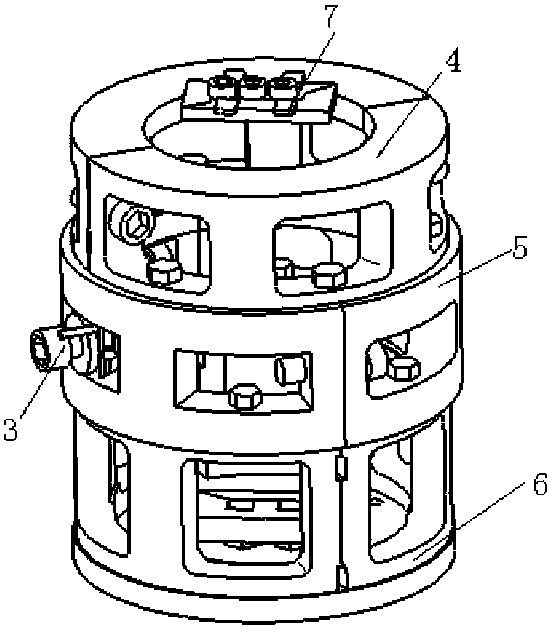
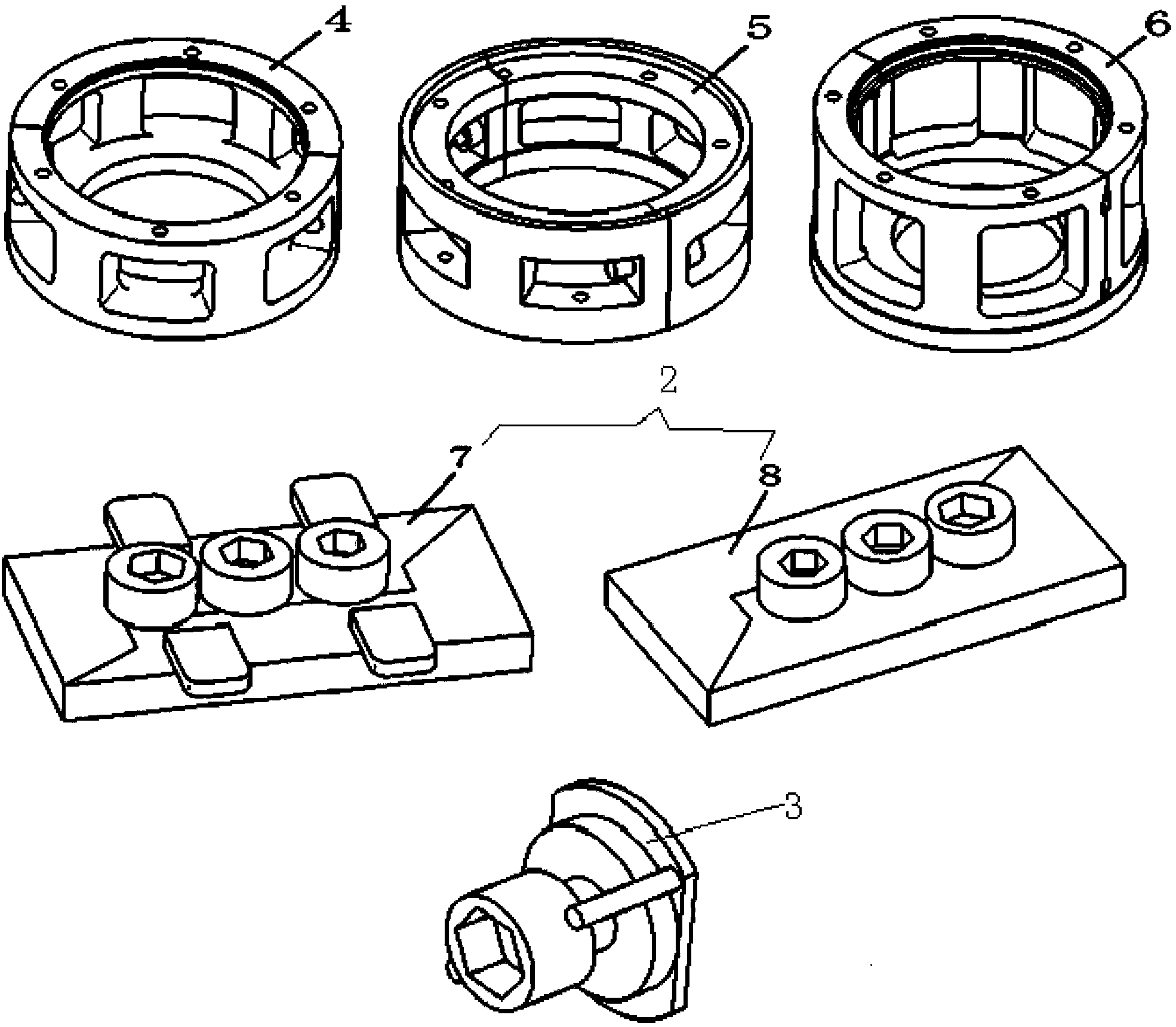
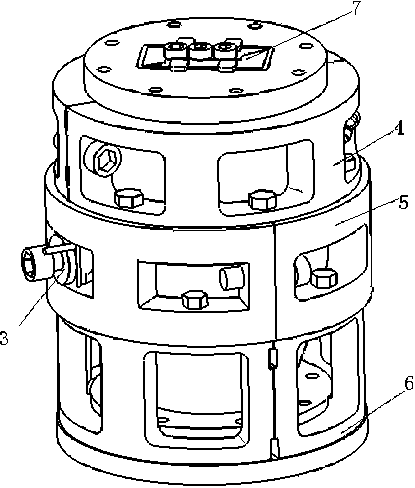
[0028] Referring to the accompanying drawings, a set of assembly and welding tooling for ceramic windows includes a main body tooling mold for fixing the surroundings of the ceramic window form, an inner cavity support structure 2 for fixing the upper and lower ends of the ceramic window form, and a baffle plate 3 for fixing the cooling water joint. The main tooling mold is composed of three tooling units, which are upper tooling unit 4 , middle tooling unit 5 and lower tooling unit 6 . The upper tooling unit 4, the middle tooling unit 5 and the lower tooling unit 6 are all composed of two semicircular structures, which are fixed in pairs after pairing, and the inner holes after the pairing are all stepped holes, and the diameter of the stepped holes is the same as that of ceramic windows and windows. The circular waveguide section in the body fits. The inner cavity support structure 2 is composed of an upper waveguide inner cavity support structure 7 and a lower waveguide inn...
PUM
 Abstract
Description
Claims
Application Information