
Coast wave absorbing group pile structure

A technology of coastal and group piles, applied in the direction of coastline protection, shore piers, shore walls, etc., can solve problems such as pollution, limited role of embankment engineering, damage to the seabed environment, etc.

Inactive Publication Date: 2013-08-21
HOHAI UNIV
View PDF3 Cites 8 Cited by
  • Summary
  • Abstract
  • Description
  • Claims
  • Application Information

AI Technical Summary

Problems solved by technology

[0003] In marine engineering, the existing method of resisting wind and wave invasion is to build a continuous earth-rock structure breakwater, but this method has the following disadvantages: 1. The project is huge, destroys the seabed environment of the relevant sea area, and blocks the exchange and self-purification function of the water body; Same as 2. The project budget is often uncontrollable; 3. After the completion of the breakwater, the function is single, and it often plays a limited role in the face of huge waves whose wave height is much greater than the height of the embankment crest: generally, the existing breakwaters and breakwaters prevent waves The height of the sea is 2 to 3 meters, but in extreme cases, the height of the waves can reach ten meters or even tens of meters. At this time, the role of traditional embankment engineering is very limited. Because the coastline is too long, it is impossible to build higher and longer breakwaters accomplish
To sum up, it can be seen that the existing anti-wave and anti-wave technology cannot well deal with the threat of marine disasters. Therefore, there is an urgent need to combine engineering technical issues and economic issues to develop a wave-dissipating and anti-wave structure with good performance.
[0004] In addition, whether the existing breakwater is in the construction process or in the process of use, it will cause major changes in the local topography and damage to the aquatic ecosystem, and will also cause the loss of the self-purification and exchange function of the water body in the enclosed area, resulting in extensive water pollution
Moreover, the transportation and migration of large volumes of sand and gravel involved in the construction process is also a corresponding pollution process, and after a certain period of service, the maintenance, replacement and demolition of traditional breakwaters will also cause considerable engineering and environmental problems

Method used


Image

  • Coast wave absorbing group pile structure
  • Coast wave absorbing group pile structure
  • Coast wave absorbing group pile structure

Examples


Embodiment Construction

[0042] The accompanying drawings disclose, without limitation, the structural schematic diagrams of the preferred embodiments involved in the present invention; the technical solution of the present invention will be described in detail below in conjunction with the accompanying drawings.

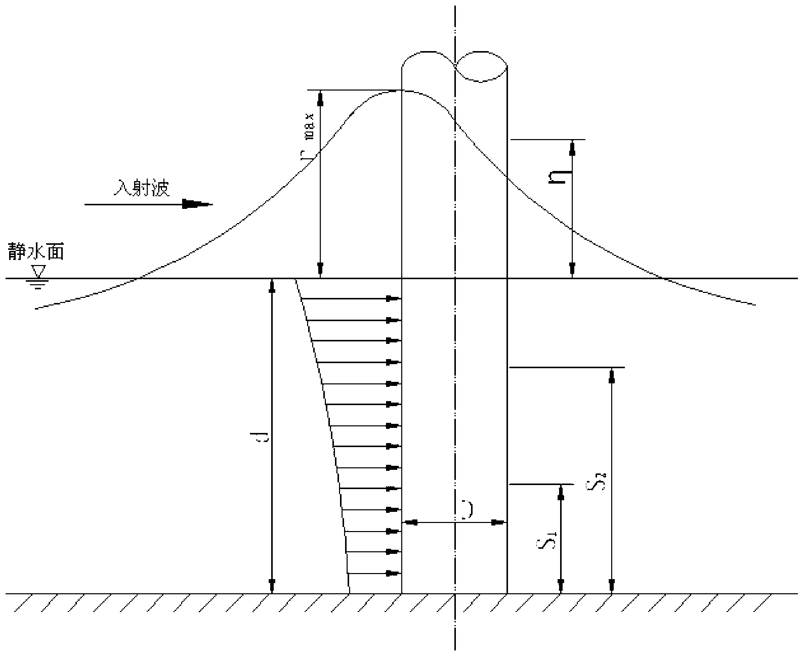
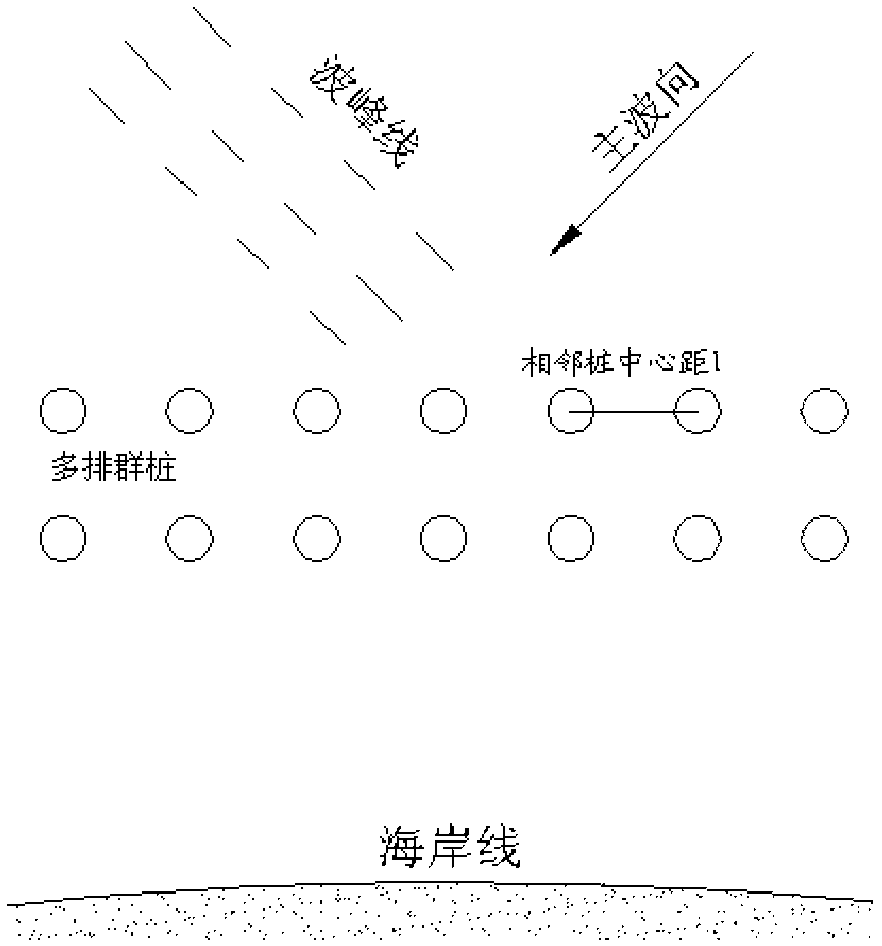
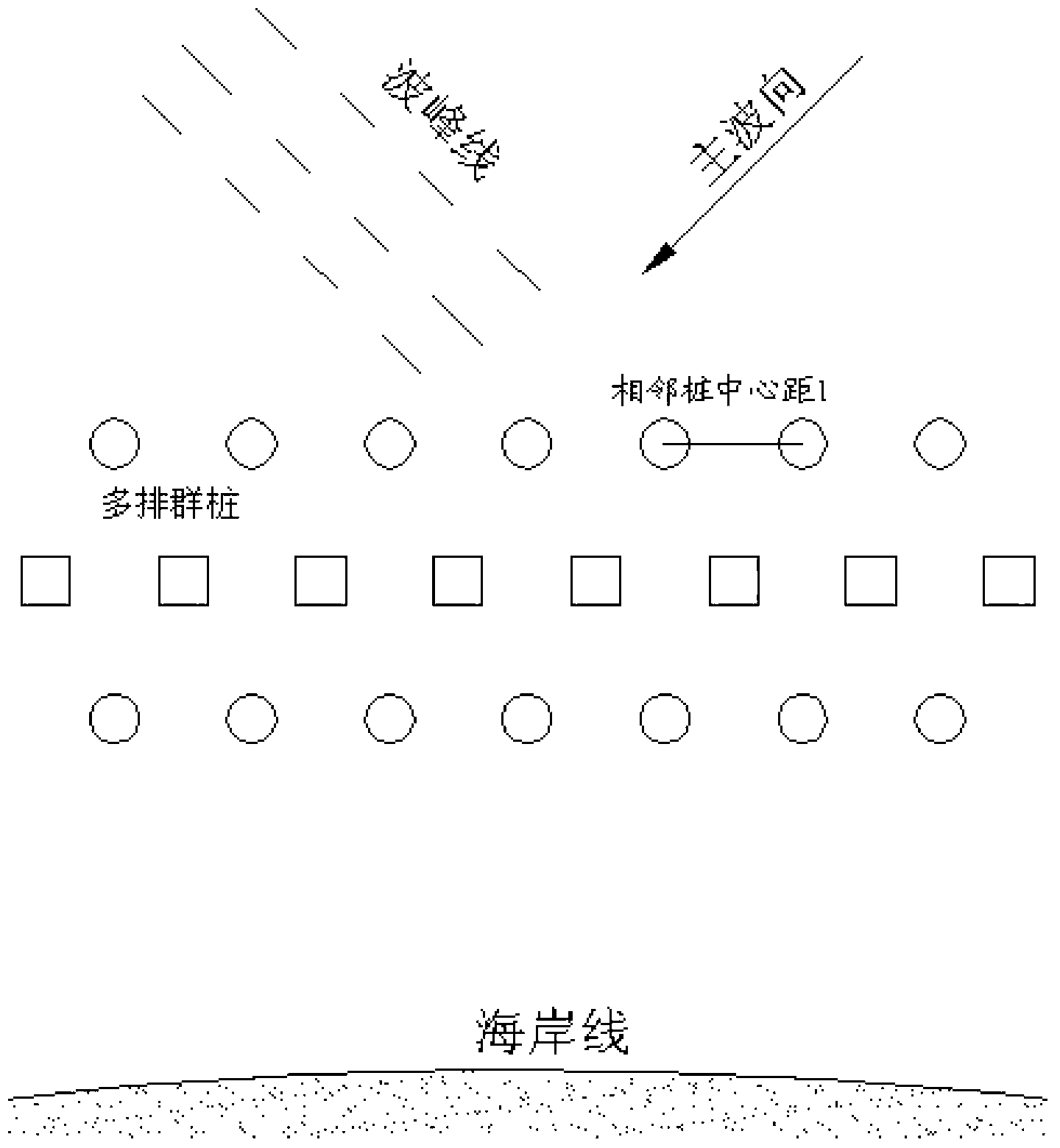
[0043] According to the specific situation, fully consider and design according to the lateral load borne by the pile, the properties of the entire soil layer through which the pile passes, the resistance coefficient of the pile side soil, the bending stiffness and strength of the pile body, among which the section size of the pile, Pile spacing and pile placement are major aspects of the design.

[0044] The construction of the pile group structure adopts prefabricated pile technology, and the construction scheme is formulated by referring to the construction methods of offshore platforms, cross-sea bridge piers and other high-pile underwater structures.

[0045] Concrete design steps of t...


PUM


Abstract

The invention provides a coast wave absorbing group pile structure which comprises a pier group which is distributed on a coast in a discrete mode. Piers of the pier group are distributed in the direction of main waves, and distribution of the piers is determined according to horizontal wave force borne by pile bodies. According to the coast wave absorbing group pile structure, reflection and diffraction on the pile bodies of the waves and inner turbulent fluctuation of fluid among the pile bodies are fully used, a moving mode of the waves is changed, wave energy is consumed, wave height is lowered, and a bottom sand starting conveying mode, a suspended sand distributing mode and a sand conveying mode under the effect of the waves are changed.

Description

technical field [0001] The invention relates to a pile group structure for wave dissipation and anti-wave on the coast, which can be widely used in the construction of offshore anti-wave engineering, can reduce the wave load borne by port structures, reduce the top height of embankments and dams, reduce the cross-sectional area, and The harbor protection basin maintains a stable water surface and protects port operations from waves and ice edges. It effectively saves investment and also plays a role in preventing tidal erosion, protecting beaches and promoting silting, and protecting the environment. Background technique [0002] When analyzing the external force of offshore buildings or structures, it is necessary to consider the random characteristics of various dynamic factors because of the influence of climate factors such as tides, typhoons and tsunamis. Due to the huge cost of related projects and the serious consequences of accidents, it is not only necessary to stri...

Claims


Application Information

Patent Timeline
Patent Type & Authority Applications(China)
IPC IPC(8): E02B3/06
CPCY02A10/11
Inventor 陈文杨毅诚
Owner HOHAI UNIV
Learn More