Antenna switching circuit and its electronic device and its antenna switching method

A technology for antenna switching and electronic devices, applied to electrical components, transmission systems, etc., can solve the problems of radio frequency signal transmission power loss, mechanical base connector reliability reduction, etc., to achieve the effect of reducing path loss and reducing costs

Inactive Publication Date: 2016-07-06
SHENXUN COMP KUNSHAN +1
View PDF4 Cites 0 Cited by
  • Summary
  • Abstract
  • Description
  • Claims
  • Application Information

AI Technical Summary

Problems solved by technology

[0007] The mechanical base connector (base connector 13) has the advantages of simple structure and easy use, but the reliability of the mechanical base connector gradually decreases after repeated plugging and unplugging
And the mechanical base connector causes higher loss of transmission power of the radio frequency signal

Method used


Image

  • Antenna switching circuit and its electronic device and its antenna switching method
  • Antenna switching circuit and its electronic device and its antenna switching method
  • Antenna switching circuit and its electronic device and its antenna switching method

Examples


Embodiment Construction

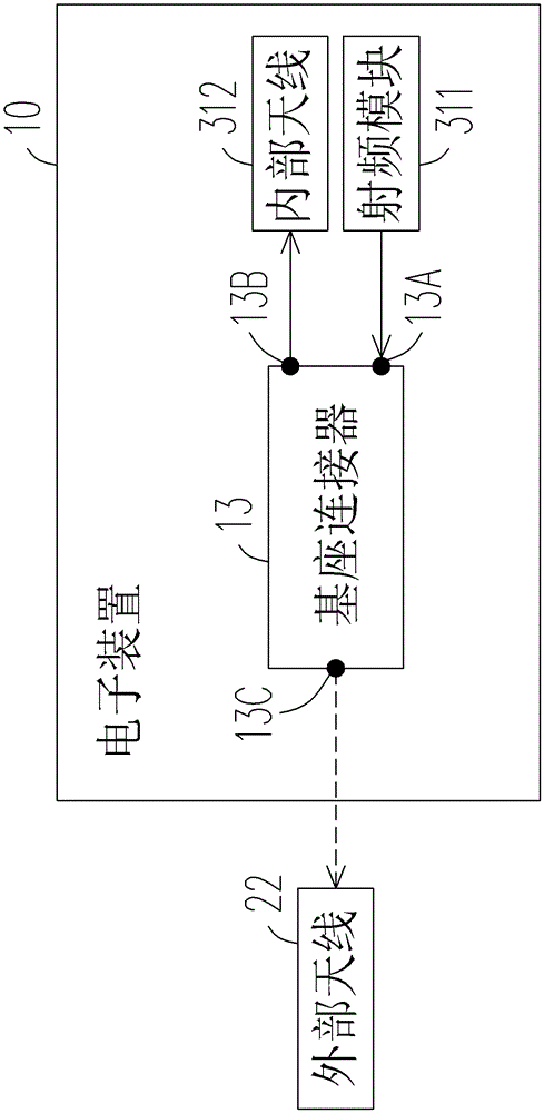
[0023] Figure 4 It is a block diagram of the electronic device of the first embodiment of the present invention. Please refer to Figure 4 , the electronic device 30 can be connected to a base device 20 (or a base system 20). The base unit 20 includes a connector 260 and an external antenna 22 .

[0024] The electronic device 30 includes an antenna switching circuit 31 , a radio frequency module 311 , an internal antenna 312 and a reference signal source 35 .

[0025] The antenna switching circuit 31 includes an external antenna connector 313 and one or more controllers 314 .

[0026] The internal antenna 312 transmits and receives radio frequency signals. The radio frequency module 311 generates or processes radio frequency signals. The controller 314 is electrically connected to the external antenna connector 313 .

[0027] The reference signal source 35 has a first ground signal GND1. In this embodiment, the first ground signal GND1 is a shared ground signal of the ...


PUM


Abstract

The invention discloses an antenna switching circuit, an electronic device of the antenna switching circuit and an antenna switching method of the antenna switching circuit. The antenna switching circuit is arranged in the electronic device which is provided with an internal antenna and a radio frequency module. The antenna switching circuit comprises an external antenna connector and at least one controller. The external antenna connector is provided with an independent grounding end for receiving independent grounding signals, and is electrically connected with an external antenna. The controller is provided with a first radio frequency end, a second radio frequency end and at least one control end. The first radio frequency end is electrically connected to the radio frequency module. The second radio frequency end is electrically connected to the internal antenna. The control end is used for detecting the independent grounding signals. When the independent grounding signals detected by the controller through the control end do not change, the controller enables the radio frequency module to be electrically connected with the internal antenna. When the independent grounding signals detected by the controller change, the controller can enable the radio frequency module to be electrically connected to the external antenna.

Description

【Technical field】 [0001] The present invention relates to an antenna switching circuit, and in particular to an antenna switching circuit connected to an external base, its electronic device and its antenna switching method. 【Background technique】 [0002] Currently, in-vehicle telematics systems or industrial computers generally use bases to improve the convenience and performance of computing devices. Please refer to figure 1 . figure 1 It is a schematic diagram of an existing electronic device connection base. The electronic device 10 includes a radio frequency module 11 , an internal antenna 12 and a base connector 13 . The base connector 13 is a mechanical base connector, which includes a first radio frequency terminal 13A, a second radio frequency terminal 13B and a third radio frequency terminal 13C. [0003] When the electronic device 10 has not been connected to the base device (not shown in figure 1 ), the first radio frequency terminal 13A is electrically con...

Claims


Application Information

Patent Timeline
Patent Type & Authority Patents(China)
IPC IPC(8): H04B1/44H04B1/40
Inventor 李彦庆邱上铭
Owner SHENXUN COMP KUNSHAN
Why Eureka
Try Eureka