Separation container and separation method

A separation container and separation method technology, applied in separation methods, chemical instruments and methods, precipitation separation, etc., can solve problems such as low sperm concentration and expensive Percoll

Inactive Publication Date: 2013-08-21
JMS CO LTD
View PDF8 Cites 6 Cited by
  • Summary
  • Abstract
  • Description
  • Claims
  • Application Information

AI Technical Summary

Problems solved by technology

Therefore, after centrifugation, there is a problem that the sperm concentration of the sperm sample remaining in the container body is low
Also, since Percoll is more expensive, there is a cost issue as well

Method used


Image

  • Separation container and separation method
  • Separation container and separation method
  • Separation container and separation method

Examples


Embodiment approach 1

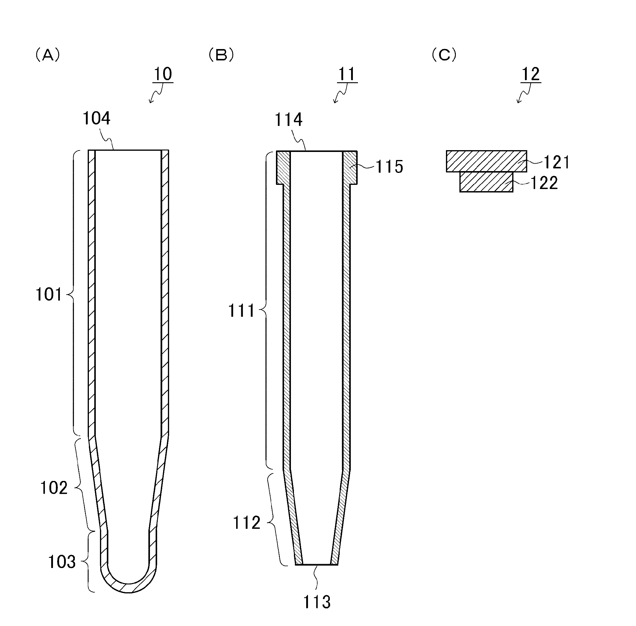
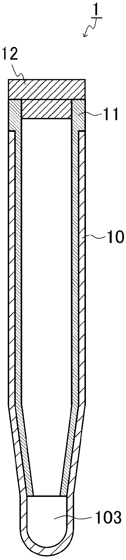
[0109] The separation container of this example is shown in figure 1 and figure 2 in the sectional view. figure 1 It is a sectional view of the member which comprises a separation container, (A) is an outer container, (B) is an inner container, (C) is a cover part. figure 2 is a cross-sectional view of the separation container.

[0110] Such as figure 1 As shown in (A), the outer container 10 has a bottomed cylindrical shape having an opening 104 at the upper end, and includes a main body 101 , a tapered portion 102 , and an accommodating portion 103 . Such as figure 1 As shown in (B), the inner container 11 has an opening 114 and an opening 113 at the upper end and the lower end respectively, and includes a main body 111 and a tapered portion 112. protrusion 115 . The protruding portion 115 serves as a gripping portion of the inner container 11, for example, as described above. In addition, the cover portion 12 is located closer to, for example, the above-mentioned u...

Embodiment approach 2

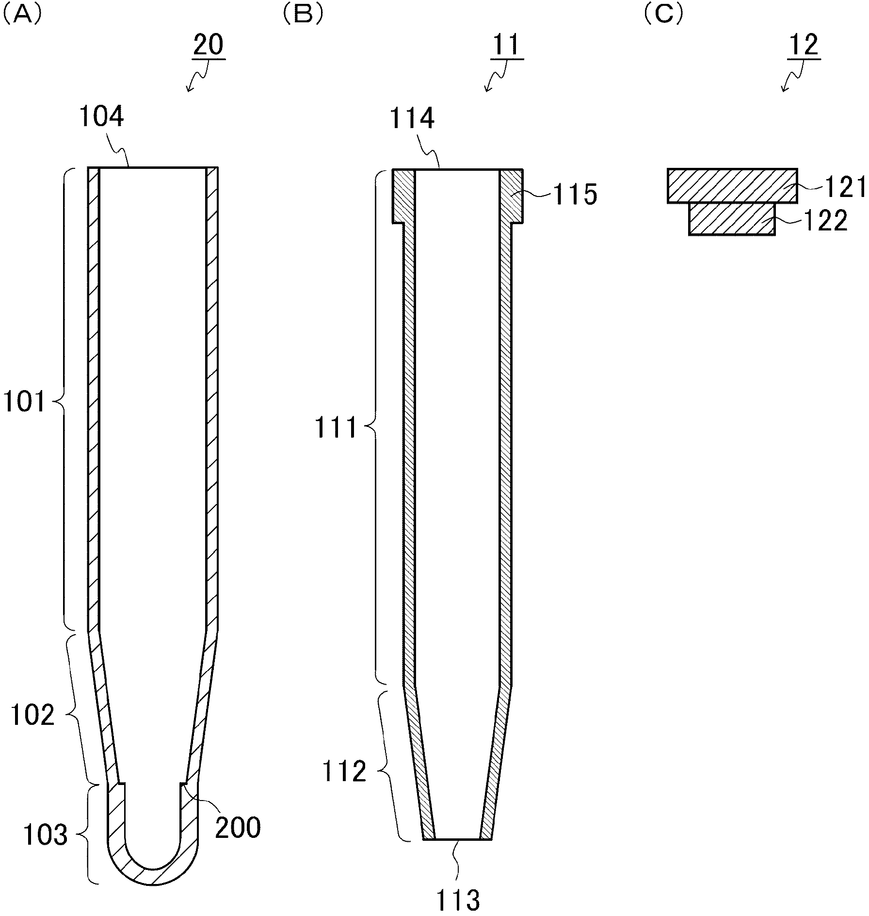
[0126] The separation container of this example is shown in image 3 and Figure 4 . image 3 It is a sectional view of the member which comprises a separation container, (A) is an outer container, (B) is an inner container, (C) is a cover part. Figure 4 is a cross-sectional view of the separation container.

[0127] Such as image 3 As shown in (A), the outer container 20 is a bottomed cylindrical shape with an opening 104 at the upper end, including a main body 101 , a tapered portion 102 and an accommodating portion 103 , and on the inner peripheral surface of the upper end of the accommodating portion 103 It has a circumferential protrusion 200 . The size of the protrusion 200 is not particularly limited. image 3 (B) and (C) with the above figure 1 (B) and (C) are the same. And, if Figure 4 As shown, in the separation container 2, the inner container 11 is disposed inside the outer container 20, and the lid 12 is attached to the upper opening.

[0128] Examples...

Embodiment approach 3

[0133] The separation container of the present embodiment is an example of a form in which the volume of the storage portion inside the outer container can be changed.

[0134] (1) Embodiment 3-1

[0135] The outer container and inner container constituting the separation container of this example are shown in Figure 6 , Figure 7 and Figure 8 (Cover not shown).

[0136] Figure 6 is a schematic diagram of the outer container, (A) is a sectional view of the outer container, (B) is a plan view of the upper part of the outer container, and (C) is a perspective view of the upper part of the outer container. Such as Figure 6 As shown in (A), the outer container 30 is a bottomed cylindrical shape having an opening 304 at the upper end, and includes a main body 301 , a tapered portion 302 and a tip 305 . And, if Figure 6 As shown in (A), (B) and (C), four engaging grooves (recesses) 306 a , 306 b , 306 c , and 306 d are formed on the upper inner peripheral surface of the ...


PUM

PropertyMeasurementUnit
heightaaaaaaaaaa
heightaaaaaaaaaa
heightaaaaaaaaaa

Abstract

Provided is a separation container capable of preventing contamination by unnecessary components and capable of efficiently separating target matter. The separation container for separating target matter from a sample has an outer container, an inner container, and a lid section and is characterized by: the outer container having a closed-end tube shape, with the top end open and the bottom end closed; the inner container having a tube shape with both the top end and the bottom end open and being arrangeable inside the outer container when both the outer container and the inner container are lined up in the vertical direction; the area below the inner container inside the outer container, when the inner container is arranged inside the outer container, being a section for housing sediment from the sample; the lid section being removable from the top end open section of the inner container; and the inside of the inner container being liquid tight when the lid section is mounted to the open section of the inner container.

Description

technical field [0001] The invention relates to a separation container and a separation method. Background technique [0002] In infertility, it is considered that male causes account for more than 50%. Examples of male infertility include azoospermia due to low concentration of sperm in semen, atonezoospermia due to lack of motility of sperm, and the like. In such cases, assisted reproductive medicine such as artificial insemination, in vitro fertilization, and micro-insemination using sperm recovered from semen is applied. [0003] Examples of methods for preparing sperm samples include a separation method using density gradient centrifugation (density gradient centrifugation method) and a separation method using sperm motility (upstream method (Japanese: スイムラップ method)). In the former, Percoll is first added to the centrifuge tube, and semen is superimposed on the above-mentioned Percoll for centrifugation. As a result, a density gradient is formed, and sperm are separ...

Claims


Application Information

Patent Timeline
Patent Type & Authority Applications(China)
IPC IPC(8): B04B5/02A61M1/02
CPCB01L3/5021B01L2200/025B01L2300/0854B01D21/262B04B7/08
Inventor 平井聪武田典子冲津摄
Owner JMS CO LTD
Why Eureka
Try Eureka