Liquid aspirator

A technology for aspirators and liquids, which is applied in the direction of vacuum cleaners, waterway systems, cleaning equipment, etc., and can solve the time-consuming problems of liquid or sludge suction

Active Publication Date: 2009-09-02
OASE GMBH
View PDF4 Cites 0 Cited by
  • Summary
  • Abstract
  • Description
  • Claims
  • Application Information

AI Technical Summary

Problems solved by technology

The suction of liquids or sludge is therefore time-consuming

Method used


Image

  • Liquid aspirator
  • Liquid aspirator
  • Liquid aspirator

Examples


Embodiment Construction

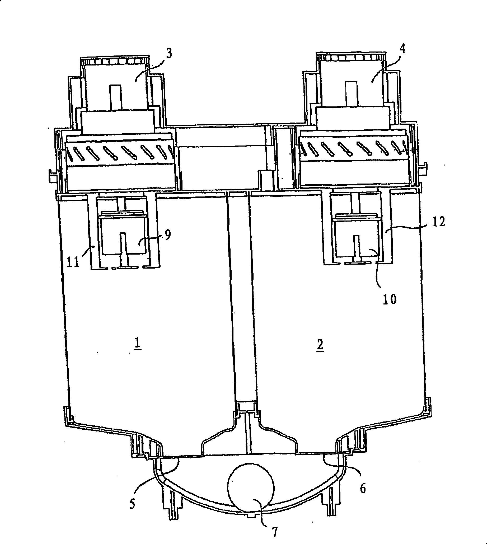
[0023] figure 1 A liquid suction device is shown schematically, which has two separate receiving chambers 1,2. An own suction motor 3,4 is provided for each material receiving chamber 1,2. A negative pressure can be created in the chambers 1, 2 by means of the suction motors 3, 4, whereby the liquid can be drawn into the receiving chamber 1, 2 via a suction connection not shown leading into the upper region of the receiving chamber 1, 2 2 within. If, for example, the receiving chamber 1 is filled to a predetermined height with liquid, the suction motor 3 is switched off. Under the self-weight effect of liquid, open a negative pressure valve 5 that closes material receiving chamber 1 at the downside, liquid flows out through outlet 7 and an unrepresented emptying member connected therewith, such as an outlet hose. The control device ensures that the material receiving chambers 1 and 2 are filled and emptied alternately, so that the liquid is continuously sucked and discharge...


PUM


Abstract

The invention relates to a liquid suction device, in particular for solid-containing liquids, such as sludge, comprising a container (13) into which the liquid can be sucked by means of a suction motor (3, 4) via a suction connection (15). 13), and the liquid can be discharged from the container (13) through the outlet (7), according to the present invention, the liquid suction device is designed so that the container (13) has at least two separate receiving chambers (1, 2) and a control device, through which one material receiving chamber (1, 2) is filled with liquid alternately, and the other material receiving chamber (2, 1) is emptied during this period. The suction side of the receiving chamber (1, 2) relative to the suction motor (3, 4) can be sealed by the main valve, which is preferably mechanically connected.

Description

technical field [0001] The invention relates to a liquid suction device for suctioning or transporting liquids, in particular solids-containing liquids such as sludge. Background technique [0002] Such a liquid aspirator according to the preamble of claim 1 is known from DE 102 40 804 A1. It has a container in which negative pressure is created by a suction motor. The liquid or sludge is sucked into the container via the suction connection by negative pressure, and, after the container is full and the motor is switched off, the liquid or sludge can be drained out of the container again via an outlet and an emptying part, usually in the form of a hose. Navigate to the required location. [0003] This type of sludge suction works reliably because the motor is separated from the liquid or sludge to be moved by the container, which prevents the motor from being damaged by accompanying solids. However, after each filling process of the container there must be a suction break ...

Claims


Application Information

Patent Timeline
Patent Type & Authority Patents(China)
IPC IPC(8): A47L7/00E03F7/10
CPCA47L7/0038A47L7/0028A47L7/0042
Inventor D·霍夫迈尔R·韦塞尔迈尔U·瓦格纳
Owner OASE GMBH
Why Eureka
Try Eureka