
Clamping device

A technology for clamping equipment and tensioning arms, used in clamps, manufacturing tools, clothing, etc.

Inactive Publication Date: 2015-03-11
DE STA CO METALLERZEUGNISSE GMBH
View PDF12 Cites 0 Cited by
  • Summary
  • Abstract
  • Description
  • Claims
  • Application Information

AI Technical Summary

Problems solved by technology

However, it is also not possible to release the tensioned clamping device from its off-center position if the operating tool fails

Method used


Image

  • Clamping device
  • Clamping device
  • Clamping device

Examples


Embodiment Construction

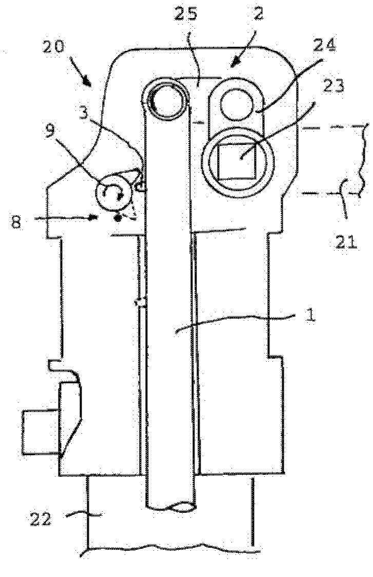
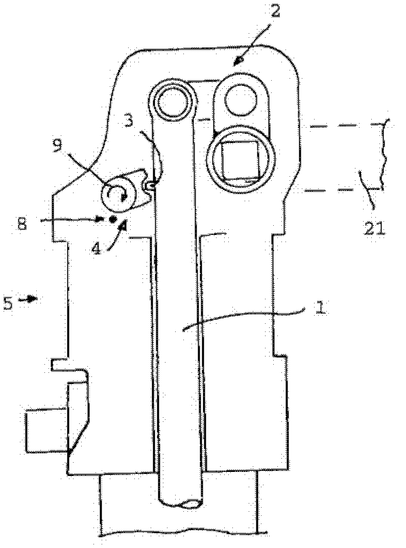
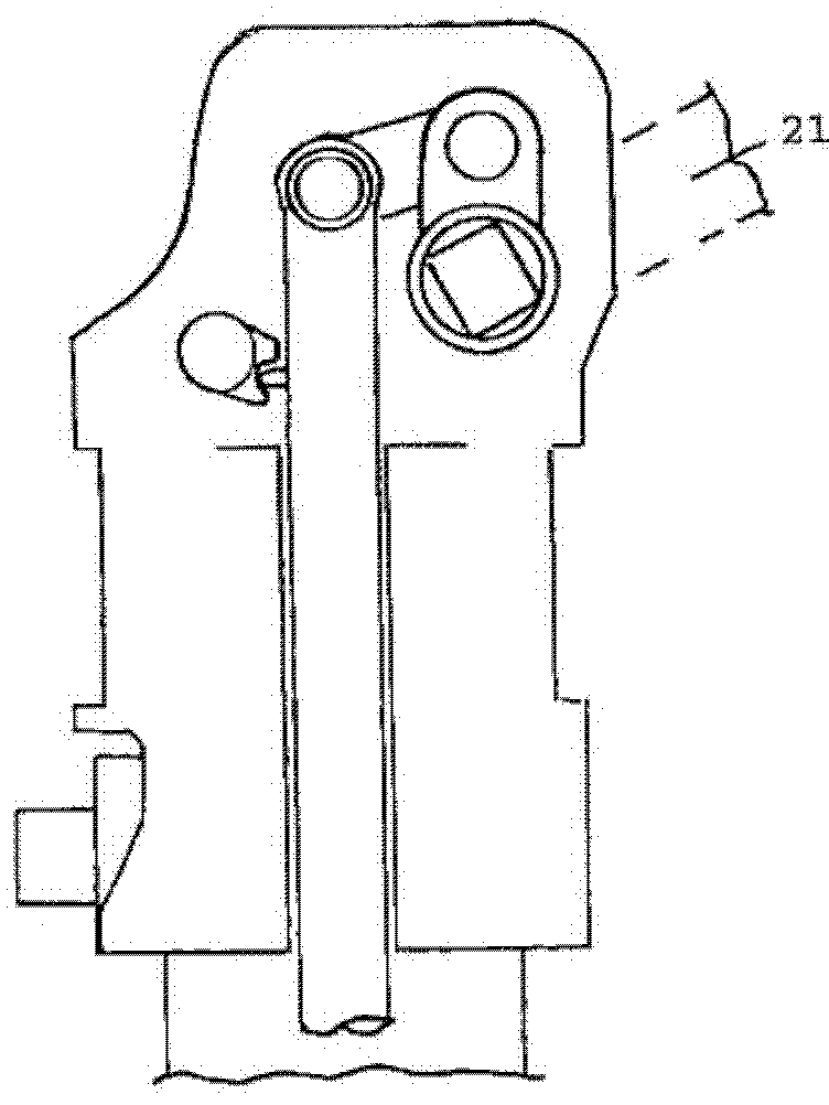
[0018] exist Figures 1 to 4 The clamping device exemplified in a highly schematic manner in , generally consists of a toggle lever mechanism 2 housed in a head member 20 and provided with a drive 22 (such as a reciprocating piston) that can pass through (in particular pneumatic) Actuator 1 for linear movement, wherein the toggle lever mechanism is assigned means for unlocking from an eccentric position. These means consist of a control member 3 and a rocker 4 which can be adjusted into contact with the control member 3 . The control mechanism 2 also generally features an intermediate member 25 for creating the connection between the actuator 1 and the shaft 24 with the pivot 23 of the tensioning arm 21 .

[0019] In this clamping device it is important that the control member 3 is realized as a control extension in a direction away from the pivot and that the actuator 1 is arranged between the pivot 23 and the rocker 4, ie , the rocker 4 is realized such that it can be actu...


PUM


Abstract

A clamping device has a toggle lever mechanism (2) with a linearly movable actuator (1) and a pivot shaft (23) with a tensioning arm (21). A mechanism to unlock an over-center position is coupled with the toggle lever mechanism. The mechanism includes a control element (3) that is arranged on the actuator (1) and a rocker (4). The rocker (4) can be brought into adjusting contact with the control element (3). The control element (3) is in the form of a control extension in a direction facing away from the pivot shaft. The actuator (1) is arranged between the pivot shaft (23) and the rocker (4).

Description

technical field [0001] The present invention relates to clamping devices. Background technique [0002] This type of clamping device essentially consists of a head member, and a drive member arranged on it, wherein a linearly movable actuator and a tensioning arm can be actuated by a drive, and by means of a head member arranged on the The adjustment mechanism in the device converts linear adjustment into pivotal movement of the tensioning arm of the device, which can usually be adjusted into an off-center position, thereby maintaining its grip in the event of failure of the operating tool used for driving, for whatever reason. tight position. However, it is also not possible to release the tensioned clamping device from its off-center position if the operating tool fails. This is why clamping devices of this type are usually equipped with means that can reset or unlock the clamping device from the off-center position. In this respect, reference is made to the following p...

Claims


Application Information

Patent Timeline
Patent Type & Authority Patents(China)
IPC IPC(8): B25B5/12
CPCB25B5/122Y10T24/44966
Inventor D·乌列
Owner DE STA CO METALLERZEUGNISSE GMBH
Learn More