Low-energy-consumption high-light-intensity annular light-emitting cavity fluorescent lamp

A low-energy, fluorescent lamp technology, applied in the field of fluorescent energy-saving lamps, can solve the problems of increased energy consumption, increased lamp tube diameter, and decreased light efficiency, achieving the effect of increased diameter, increased polygonal sides, and reduced light efficiency.

Inactive Publication Date: 2012-03-28
陈坚
View PDF3 Cites 0 Cited by
  • Summary
  • Abstract
  • Description
  • Claims
  • Application Information

AI Technical Summary

Problems solved by technology

In addition, increasing the diameter of the lamp tube can also rapidly increase the area of ​​the phosphor and obtain a light source with a higher light density, but the increase in the diameter of the lamp tube will greatly reduce the luminous efficiency and greatly increase the energy consumption.
How to obtain energy-saving and high-efficiency fluorescent lamps has always been a subject of research in the industry, and such products have not yet been seen on the market

Method used


Image

  • Low-energy-consumption high-light-intensity annular light-emitting cavity fluorescent lamp
  • Low-energy-consumption high-light-intensity annular light-emitting cavity fluorescent lamp
  • Low-energy-consumption high-light-intensity annular light-emitting cavity fluorescent lamp

Examples


Embodiment 1

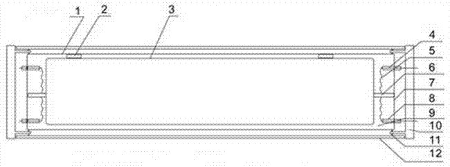
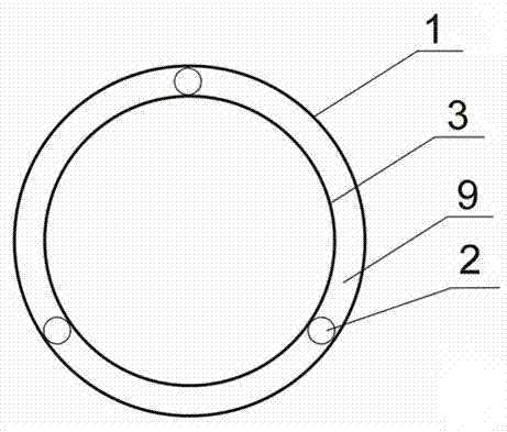
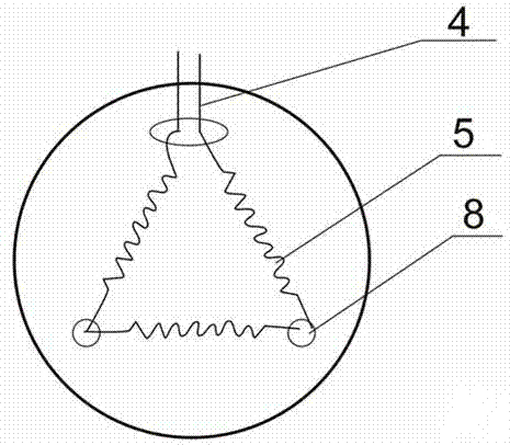
[0024] Depend on Figure 1-3 As shown, 1 in the figure is a phosphor glass outer tube coated on the inside, and a coaxial closed inner tube 3 is arranged on the inner side of the phosphor glass outer tube 1, and the phosphor glass outer tube 1 and the closed inner tube 3 There is also a positioning rod 2 forming an annular gap 9 between them, and an inner end cap 7 with a conductive filament connection line 4 is respectively provided at the two ends of the phosphor glass outer tube 1, and an inner end cap 7 with a conductive filament connection line 4 is provided at the two ends of the phosphor glass outer tube 1. A polygonal filament 5 is also arranged between the inner end cap 7 and the two ends of the closed inner tube 3 (the polygonal filament 5 can be triangular, quadrangular, pentagonal or hexagonal, etc., depending on the diameter of the lamp tube) , the larger the tube diameter, the more sides) the filament holder 8. Between the inner end caps 7 at the two ends of the...


PUM


Abstract

A low-energy-consumption high-light-intensity annular light-emitting cavity fluorescent lamp comprises a fluorescent powder glass tube, a filament support, a filament and a binding post, and has the technical key points that a concentric closed inner tube is arranged at the inner side of the glass tube coated with fluorescent powder at the inner side; an annular slotted positioning rod is arranged between the fluorescent powder glass tube and the closed inner tube; an inner end cap with a conductive filament connecting wire is arranged at each of two end parts of the fluorescent powder glass tube; and the filament support with the filament is arranged between the inner end caps at two end parts of the fluorescent powder glass tube and two ends of the closed inner cap. As the large-diameter double-layer glass tube is adopted, and the fluorescent powder is coated on the outer layer of the glass tube, election current is generated in an annular slot between the inner layer and the outer layer of the glass tube; and as the annular area is designed to be very small, sufficient fluorescent powder excitation energy can be obtained by only less election current, so that the fluorescent powder can emit rated light so as to arouse a large area of fluorescent powder to emit light, thereby obtaining a high-efficient energy-saving fluorescent source.

Description

technical field [0001] The invention relates to the field of fluorescent energy-saving lamps, in particular to a fluorescent lamp with a ring-shaped light-emitting cavity with low energy consumption and high light intensity. Background technique [0002] As we all know, the invention of fluorescent lamps and the use of lighting have a long history. Since fluorescent lamps emit light by using a small amount of electron flow to excite mercury vapor, mercury vapor emits a small amount of ultraviolet rays, and ultraviolet rays excite fluorescent powder to emit bright light. The light emitted by thermal excitation, so fluorescent lamps are very energy-saving, and have become energy-saving lamps widely used in the market. But fluorescent lamps can only be used as low-power lamps, and cannot be used as high-power lamp sources. The luminous power of a fluorescent lamp is determined by the area of ​​the fluorescent powder that emits light. Increasing the length of the tube can incre...

Claims


Application Information

Patent Timeline
Patent Type & Authority Applications(China)
IPC IPC(8): H01J61/42H01J61/067H01J61/34
Inventor 陈坚
Owner 陈坚
Why Eureka
Try Eureka