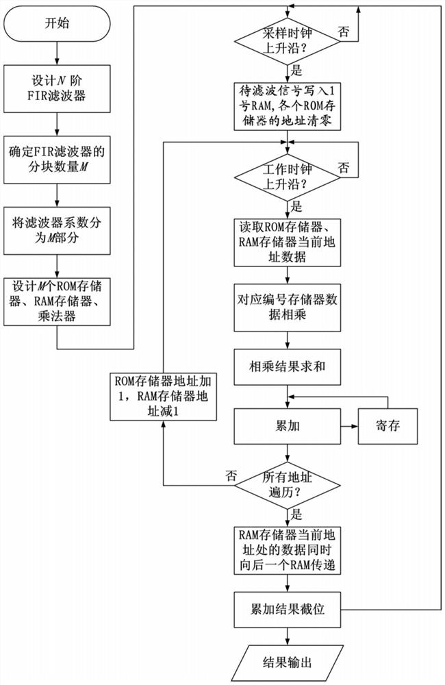
Implementation method of any-order FIR filter based on FPGA
An implementation method and filter technology, applied in impedance networks, digital technology networks, electrical components, etc., can solve problems such as poor performance and constraints on FIR filter design, and achieve the effect of both computing speed and resource consumption
- Summary
- Abstract
- Description
- Claims
- Application Information
AI Technical Summary
Problems solved by technology
Method used
Image
Examples
Embodiment
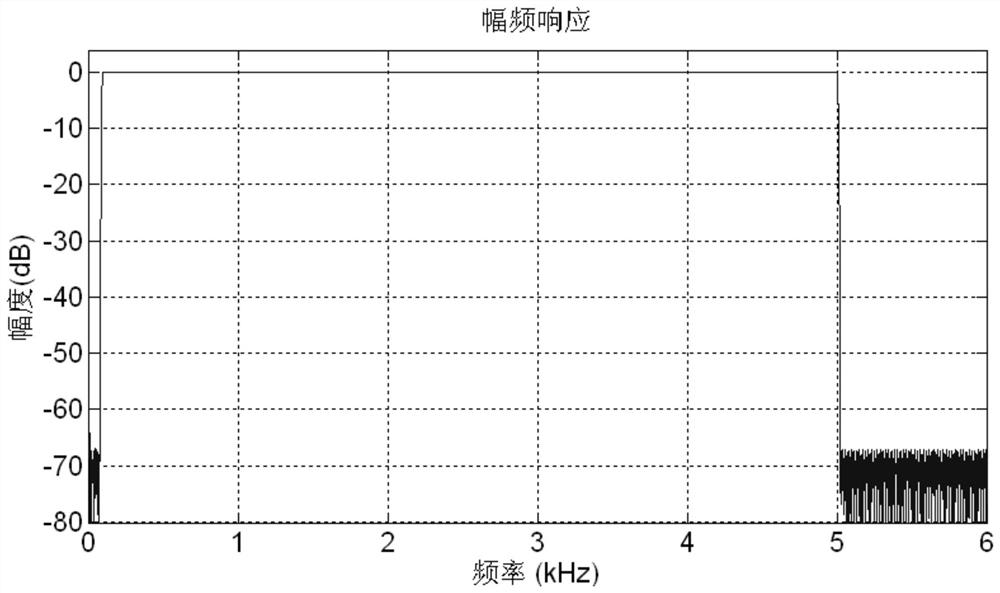
[0087] like image 3 The amplitude frequency response view of a FIR band pass filter is shown in the passband frequency range of 100 Hz-5kHz, and the bilateral transition strip is 20 Hz. Since the transition zone is narrower, the low frequency cutoff frequency is low, so the number of filters is higher, and is 9,500 order. Using the above steps to implement the design filter, the FPGA's working clock is 100MHz, the signal sample rate is 50 kHz, and the design multiplier pipeline is 4, then the number of pieces of blocks of the FIR filter can be calculated:
[0088]
[0089] So M take 5. Further, the number of filter coefficients included in each block can be calculated:
[0090]
[0091] So take N 1 = N 2 = N 3 = N 4 = 1901, N 5 = 1897.
[0092] Design 5 ROM memory, the depth is 1901 (address range is 0-1900), and 5 parts of the FIR filter coefficient are stored, and the 1897-1900 address of the 5 ROM memory is filled.
[0093] Use the standard sine wave of the amplitude 1 Vp-P...
PUM
 Abstract
Description
Claims
Application Information
 - R&D
- Intellectual Property
- Life Sciences
- Materials
- Tech Scout
- Unparalleled Data Quality
- Higher Quality Content
- 60% Fewer Hallucinations
Browse by: Latest US Patents, China's latest patents, Technical Efficacy Thesaurus, Application Domain, Technology Topic, Popular Technical Reports.
© 2025 PatSnap. All rights reserved.Legal|Privacy policy|Modern Slavery Act Transparency Statement|Sitemap|About US| Contact US: help@patsnap.com


