Method for the operation of a transmission device in a vehicle drive train

一种变速装置、车辆动力的技术,应用在车辆变速箱、传动装置、传动装置控制等方向,达到低操作成本、简单方式和方法、避免变速器状态的效果

Active Publication Date: 2013-08-21
ZF FRIEDRICHSHAFEN AG
View PDF10 Cites 4 Cited by
  • Summary
  • Abstract
  • Description
  • Claims
  • Application Information

AI Technical Summary

Problems solved by technology

However, this is not possible at every moment in the shifting process in which the form-locking shifting elements are to be opened or closed to form the desired target transmission ratio, because The form-locking shifting element cannot be opened again from a certain point in time due to the build-up of torque when closing and cannot be opened without an additional synchronization phase in the area of ​​the shifting element after the form-locking connection has been completely released during the opening phase. to its closed operating state

Method used


Image

  • Method for the operation of a transmission device in a vehicle drive train
  • Method for the operation of a transmission device in a vehicle drive train
  • Method for the operation of a transmission device in a vehicle drive train

Examples


Embodiment Construction

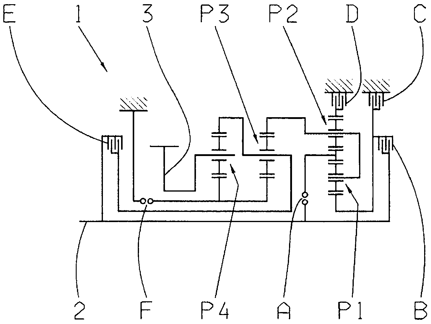
[0018] figure 1 A schematic diagram of the gears of the transmission 1 or of the multi-stage transmission known in principle from DE 10 2008 000 429 A1 is shown. The transmission 1 comprises a drive shaft 2 , which is connected to an output of the vehicle in the installed state in the vehicle, and a driven shaft 3 , which is operatively connected to the engine.

[0019] Furthermore, the transmission 1 comprises four planetary gear sets P1 to P4, the first and second planetary gear sets P1, P2, which are preferably configured as planetary gear sets with a negative gear ratio, form a switchable front gear set, while the third and second The four planetary gear sets P3, P4 constitute the main gear set. Furthermore, the transmission 1 comprises six shifting elements A to F, of which shifting elements C, D and F are in the form of brakes and shifting elements A, B and E are in the form of shifting clutches.

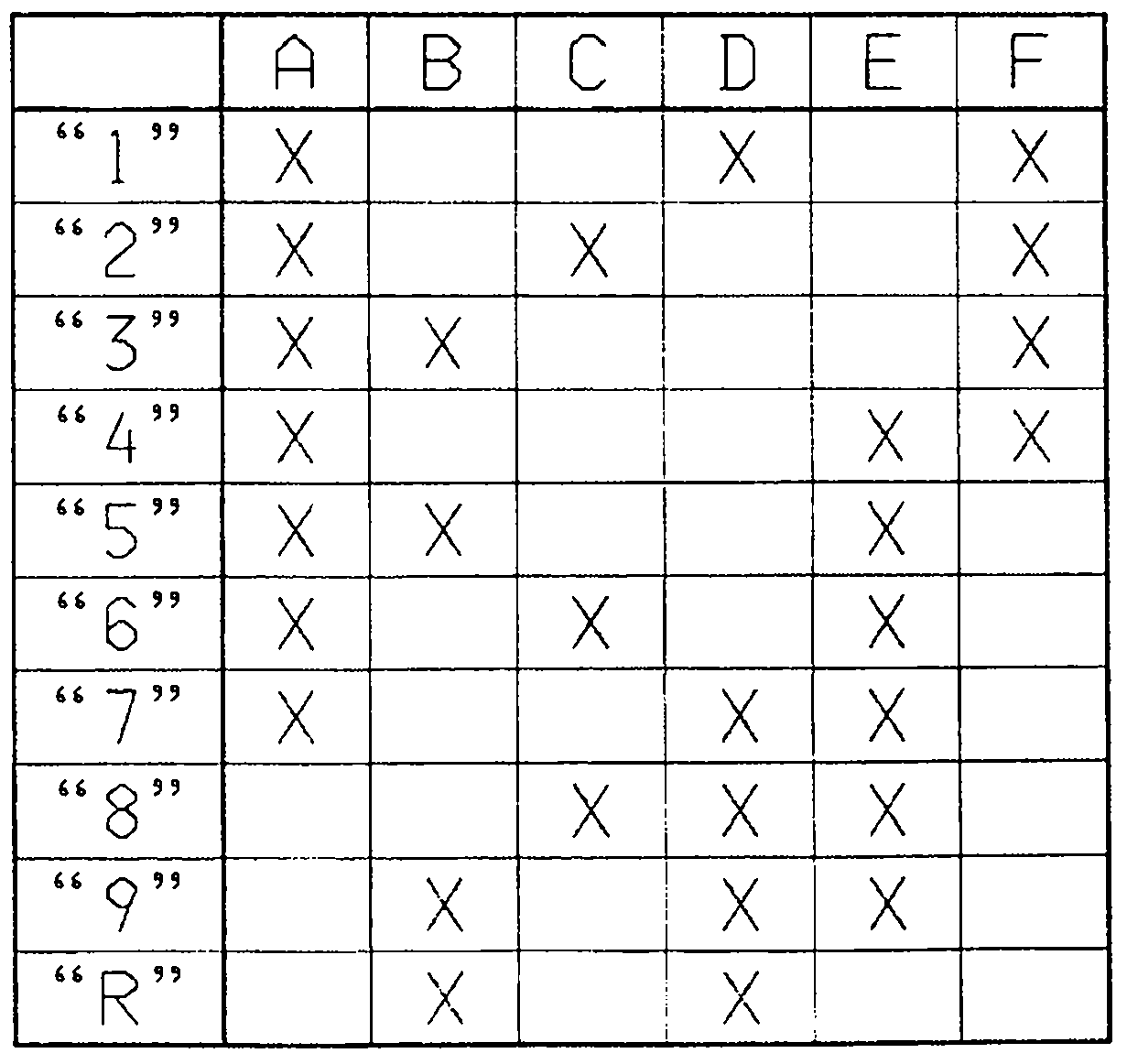
[0020] According to figure 2 The shifting logic described in detail i...


PUM


Abstract

A method for operating a transmission device (1) in a vehicle drive train is described, said transmission device (1) comprising multiple frictionally engaged shifting elements (B, C, D, E) and at least one form-fitting shifting element (A, F) which are connected or disconnected to implement various gears. When a request is made to change gears from an actual gear in the direction of a target gear and the at least one form-fitting shifting element (A, F) has to be connected to meet said request, and when a subsequent request is made to engage the actual gear in the transmission device (1) during an engagement phase of the form-fitting shifting element (A, F), said engagement phase being triggered as a result of the previous request to engage the target gear, a current operating state of the form-fitting shifting element (A, F) is determined. If a current operating state of the form-fitting shifting element (A, F) is determined in which the engagement phase can be interrupted and the form-fitting shifting element (A, F) can be disconnected, the form-fitting shifting element (A, F) is disconnected. If a current operating state of the form-fitting element (A, F) is determined in which the engagement phase of the form-fitting shifting element (A, F) has to be completed and the form-fitting shifting element (A, F) has to be engaged, the form-fitting shifting element (A, F) is connected and / or the power flow in the transmission device (1) is interrupted.

Description

technical field [0001] The invention relates to a method for operating a transmission of a vehicle powertrain according to the type defined in detail in the preamble of claim 1 . Background technique [0002] DE 10 2005 002 337 A1 discloses a transmission in the form of an eight-speed multi-stage transmission, which has friction-locking shifting elements, such as multi-plate clutches and multi-plate brakes. When there is a shift request for a transmission ratio change in the transmission, at least one frictional shifting element, which is currently engaged in the transmission in order to form The actual transmission ratio above is already connected to the power flow of the transmission; while at least one other friction-locking shift element is connected to the power flow of the transmission in order to form the required actual transmission ratio, the at least one other friction-locking The shifting element is disconnected from the power flow of the transmission when formin...

Claims


Application Information

Patent Timeline
Patent Type & Authority Applications(China)
IPC IPC(8): F16H61/04
CPCF16H61/16F16H61/686F16H2059/462F16H2059/6807F16H2200/2094F16H3/66F16H2003/442F16H2200/2064F16H61/68
Inventor G·米哈奇J·阿诺尔德
Owner ZF FRIEDRICHSHAFEN AG
Why Eureka
Try Eureka