endoscopic device
An endoscope and objective lens technology, applied to the field of endoscope devices, can solve the problem of not disclosing observation conditions and the like
- Summary
- Abstract
- Description
- Claims
- Application Information
AI Technical Summary
Problems solved by technology
Method used
Image
Examples
no. 1 Embodiment approach
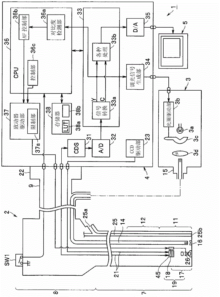
[0045] Such as figure 1As shown, the endoscope device 1 includes: an endoscope 2, which is inserted into the lumen; a light source device 3, which supplies the illumination light of the endoscope 2; an image processing device (or signal processing device) 4, which is aimed at Signal processing is carried out from the signal output from the imaging unit mounted on the endoscope 2; and the monitor 5 as a display unit is input with a standard video signal (image signal) output from the image processing device 4 to display the endoscope image.
[0046] The endoscope 2 in this embodiment has an elongated insertion portion 7 to be inserted into the subject, an operation portion 8 provided at the rear end of the insertion portion 7 and operated by an operator such as an operator, and The cable part 9 from which the operation part 8 extends.
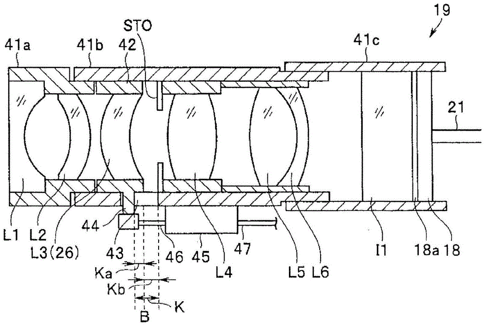
[0047] The insertion portion 7 is provided with a rigid distal end portion 11 at its distal end, and an imaging unit 19 and the like forming ...
no. 2 Embodiment approach
[0149] Next, a second embodiment of the present invention will be described. The endoscope device of this embodiment and figure 1 Compared with the endoscope device 1 of the first embodiment shown, the objective optical system and the CCD are different. In this embodiment, the Figure 9 The objective optical system 17B shown also employs a CCD 18B whose pixel pitch P is 2.3 μm.
[0150] in addition, Figure 9 (A) and Figure 9 (B) is a cross-sectional view of the objective optical system 17B in the state set to the 1st focus position and the 5th focus position, respectively. The front lens group G1 of objective optical system 17B is made of concave lens L1, parallel plate L2 and convex lens L3 (26), and rear lens group G2 is made of diaphragm, convex lens L4, the cemented lens that is formed by convex lens L5 and concave lens L6, and parallel plate L7. In addition, flat optical elements I1 and I2 are arranged behind the parallel flat plate L7, and a CCD 18B having a mosai...
no. 3 Embodiment approach
[0162] Next, a third embodiment of the present invention will be described. and figure 1 Compared with the endoscope apparatus 1 of the first embodiment shown, the endoscope apparatus of this embodiment differs in the objective optical system and the CCD. In this embodiment, the Figure 12 The objective optical system 17C shown also employs a CCD 18C whose pixel pitch P is 1.4 μm.
[0163] in addition, Figure 12 (A) and Figure 12 (B) is a cross-sectional view of the objective optical system 17C in the state set to the 1st focus position and the 4th focus position, respectively.
[0164] The front lens group G1 of the objective optical system 17C is composed of a concave lens L1, a concave lens L2, and a convex lens L3 (26), and the rear lens group G2 is composed of a diaphragm, a convex lens L4, a cemented lens formed by a convex lens L5 and a concave lens L6, and parallel plates L7, L8. . In addition, flat optical elements I1 and I2 are arranged behind the parallel fl...
PUM
 Abstract
Description
Claims
Application Information
 - R&D
- Intellectual Property
- Life Sciences
- Materials
- Tech Scout
- Unparalleled Data Quality
- Higher Quality Content
- 60% Fewer Hallucinations
Browse by: Latest US Patents, China's latest patents, Technical Efficacy Thesaurus, Application Domain, Technology Topic, Popular Technical Reports.
© 2025 PatSnap. All rights reserved.Legal|Privacy policy|Modern Slavery Act Transparency Statement|Sitemap|About US| Contact US: help@patsnap.com


