Endoscope device

An endoscope and objective lens technology, applied to the field of endoscope devices, can solve the problem of not disclosing observation conditions and the like

Active Publication Date: 2013-08-21
OLYMPUS CORP
View PDF6 Cites 12 Cited by
  • Summary
  • Abstract
  • Description
  • Claims
  • Application Information

AI Technical Summary

Problems solved by technology

[0008] Therefore, in order to perform such operations smoothly, it is desired to have an endoscope device that satisfies the observation conditions tha

Method used


Image

  • Endoscope device
  • Endoscope device
  • Endoscope device

Examples


no. 1 Embodiment approach )

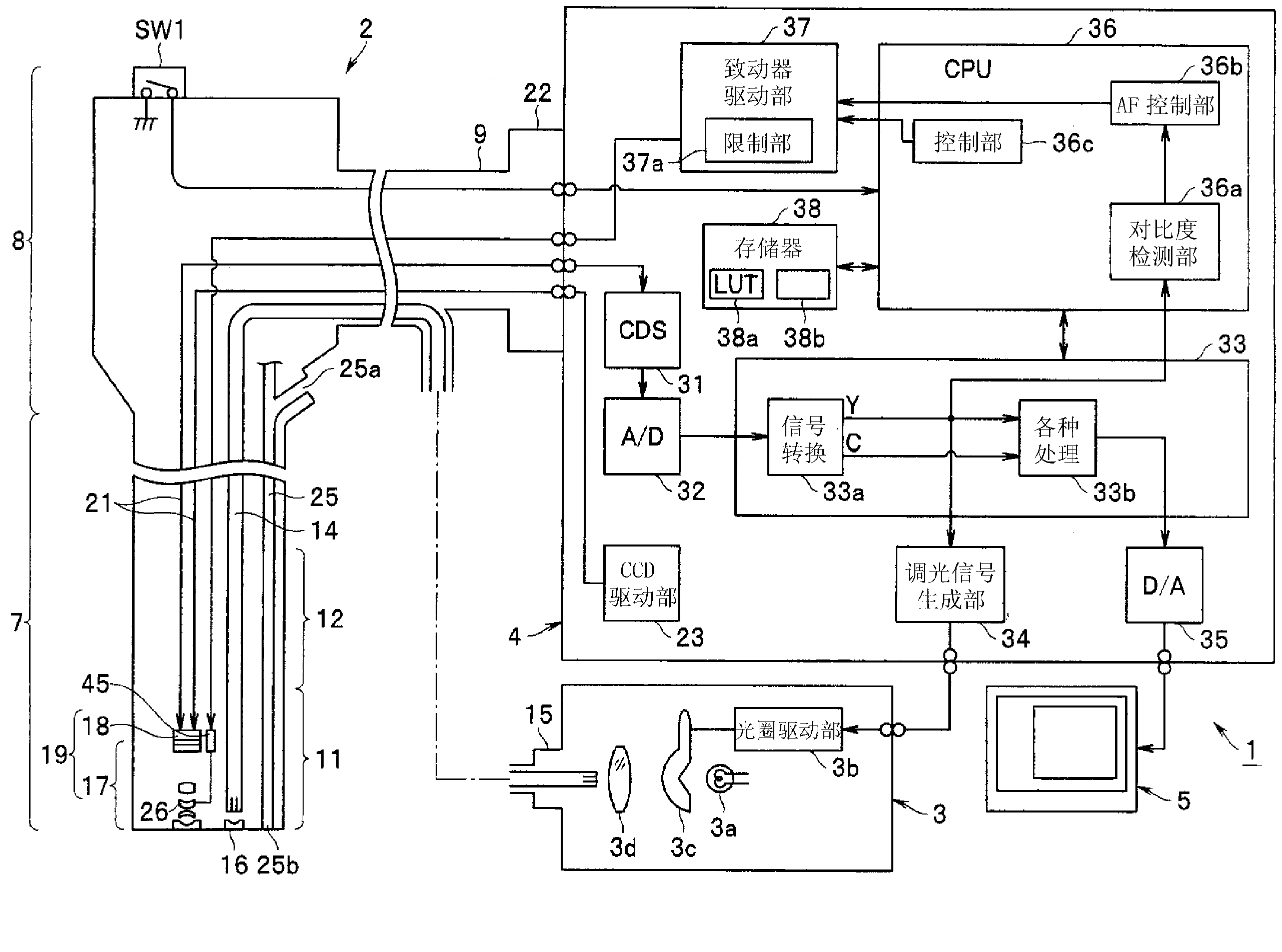
[0045] like figure 1As shown, the endoscope device 1 includes: an endoscope 2, which is inserted into the lumen; a light source device 3, which supplies the illumination light of the endoscope 2; an image processing device (or signal processing device) 4, which targets Signal processing is performed on the signal output from the imaging unit mounted on the endoscope 2; and a monitor 5 as a display unit is input with a standard video signal (image signal) output from the image processing device 4 to display the endoscope image.

[0046] The endoscope 2 in this embodiment has an elongated insertion portion 7 to be inserted into the subject, an operation portion 8 provided at the rear end of the insertion portion 7 and operated by an operator such as an operator, and The cable part 9 from which the operation part 8 extends.

[0047] The insertion portion 7 is provided with a rigid distal end portion 11 at its distal end, and an imaging unit 19 and the like forming imaging means...

no. 2 Embodiment approach )

[0150] Next, a second embodiment of the present invention will be described. The endoscope device of this embodiment and figure 1 Compared with the endoscope device 1 of the first embodiment shown, the objective optical system and the CCD are different. In this embodiment, the Figure 9 The objective optical system 17B shown also employs a CCD 18B whose pixel pitch P is 2.3 μm.

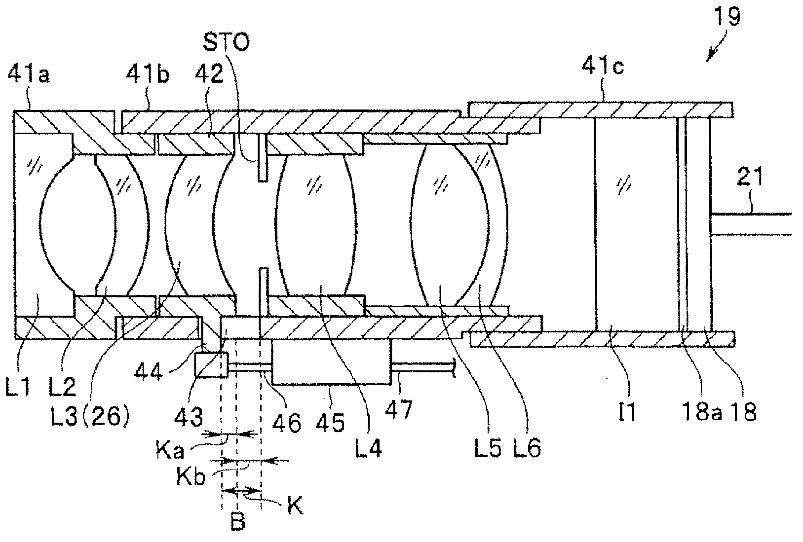
[0151] in addition, Figure 9 (A) and Figure 9 (B) is a cross-sectional view of the objective optical system 17B in the state set to the 1st focus position and the 5th focus position, respectively. The front lens group G1 of the objective optical system 17B is composed of a concave lens L1, a parallel plate L2, and a convex lens L3 (26), and the rear lens group G2 is composed of a diaphragm, a convex lens L4, a cemented lens formed by a convex lens L5 and a concave lens L6, and a parallel plate L7. In addition, flat optical elements I1 and I2 are arranged behind the parallel flat plate L7, and a...

no. 3 Embodiment approach )

[0164] Next, a third embodiment of the present invention will be described. and figure 1 Compared with the endoscope apparatus 1 of the illustrated first embodiment, the endoscope apparatus of the present embodiment is different in the objective optical system and the CCD. In this embodiment, the Figure 12 In the shown objective optical system 17C, a CCD 18C having a pixel pitch P of 1.4 μm is used.

[0165] in addition, Figure 12 of (A) and Figure 12 (B) of FIG. 1 shows a cross-sectional view of the objective optical system 17C in a state of being set to the first focal position and the fourth focal position, respectively.

[0166] The front lens group G1 of the objective optical system 17C is composed of a concave lens L1, a concave lens L2, and a convex lens L3 (26), and the rear lens group G2 is composed of a diaphragm, a convex lens L4, a cemented lens composed of a convex lens L5 and a concave lens L6, and parallel flat plates L7 and L8. . Further, flat optical ...


PUM


Abstract

An endoscope device is provided with: an objective optical system that is mounted at a tip part of an endoscope that is inserted in the lumen, and forms an image of a subject image in the lumen, said objective optical system including a focusing lens that is movable in the direction of the optical axis; a solid-state imaging element for color imaging in which a color separation filter is disposed for each pixel that images an image that has been formed by the objective optical system; a focus adjusting mechanism that adjusts the objective optical system to a focal point position for a state of focus automatically by moving the focusing lens; and the like. When the objective optical system is adjusted automatically to a focal position by the focus adjusting mechanism, the resolving power is 35 [mu]m or greater in a focal position in which the distance between the optical system and the subject is 15 mm or less, and when the range in which MTF for a spatial frequency of 1/(3XP) is 10% or greater is defined as the depth range, the objective optical system has a depth range of 5 mm or greater.

Description

technical field [0001] The present invention relates to an endoscope device with automatic focusing function. Background technique [0002] In recent years, endoscopes including imaging units using solid-state imaging elements have been widely used in the medical field. [0003] In addition, an endoscope including an optical system having an autofocus function to enable detailed observation of an affected part and the like and an imaging unit using a solid-state imaging element with increased pixels have been proposed. [0004] For example, a conventional example of Japanese Patent Laid-Open No. 2002-253489 discloses an endoscope apparatus that performs autofocus by moving a part of the lenses in the objective optical system. [0005] In the above-described conventional example, when the magnification control means is activated by the operation of the switching means, the focus control means activated in conjunction with the control signal of the magnification control means...

Claims


Application Information

Patent Timeline
IPC IPC(8): G02B7/28A61B1/00A61B1/04G02B7/36G02B23/24G02B21/02
CPCG02B7/08G02B7/36G02B23/2438G02B23/2469G02B23/2484A61B1/00096A61B1/00188A61B1/045A61B1/051A61B1/00009A61B1/0002A61B1/00045A61B1/0051A61B1/018A61B1/0661A61B1/07A61B1/00174
Inventor 笹本勉
Owner OLYMPUS CORP
Why Eureka
Try Eureka