Built-in centering chuck

A built-in, collet technology, applied in the direction of workpiece clamping devices, manufacturing tools, etc., can solve problems such as unsafe, inconvenient disassembly of discs, slow speed, etc., and achieve the effect of large clamping force

Active Publication Date: 2013-09-04
李恩典
View PDF8 Cites 4 Cited by
  • Summary
  • Abstract
  • Description
  • Claims
  • Application Information

AI Technical Summary

Problems solved by technology

In this way, not only is it inconvenient to disassemble the disc, the speed is slow, the labor intensity is high, and it is unsafe, but also the concentricity of the chuck is poor when rotating at high speed.

Method used


Image

  • Built-in centering chuck

Examples


Embodiment Construction

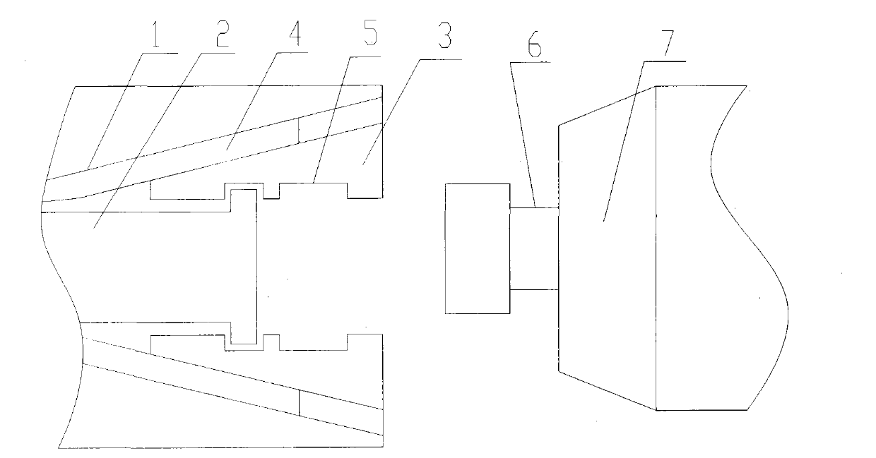
[0016] like figure 1 As shown, a built-in centering chuck, the inner inclined surface 1 of the main shaft of the built-in centering chuck is fixed with a positioning sleeve 4, and there is a sliding movable claw 3 in the movable groove of the positioning sleeve 4, and the movable claw 3 is provided with an inner Hole (not shown), the outer end face of movable claw 3 is slidingly matched with main shaft inner slope 1, and a movable push-pull rod 2 is arranged on the inside of movable claw 3, and passive protruding shaft 6 matches with inner hole (not shown). The passive protruding shaft 6 has a passive protruding shaft slope 7 on the right side. The inclination angles of the inner inclined surface 1 of the main shaft, the positioning sleeve 4, the outer surface of the movable claw 3 and the inclined surface 7 of the passive convex shaft are all between 3° and 38°. There is a groove 5 on the inner hole (not shown in the figure), and it can also be configured in other forms matc...


PUM


Abstract

The invention discloses a built-in centering chuck. A positioning sleeve is fixed on a spindle inner slope. A movable claw provided with an inner hole is slidably disposed in a movable groove of the positioning sleeve. The outer end face of the movable claw is in slide fit with the spindle inner slope. A movable push-pull rod is disposed on the inner side of the movable claw. A driven cam shaft is matched with movable claw inner hole. The driven cam shaft is provided with a driven cam shaft slope. The inclination angle of each of the spindle inner slope, the positioning sleeve, the outer side of the movable claw, and the driven cam shaft slope is in range of 3-38 degrees. A groove is formed in the movable claw inner hole which can also be matched with the driven cam shaft. The top end of the push-pull rod is provided with steps which allow the movable claw to move. Multiple such movable claws can be disposed. The built-in centering chuck is firm in clamping, capable of automatically positioning and safe, and heavy and repeated manual operations are replaced.

Description

technical field [0001] The invention relates to layer winding of metal ribbons in the industrial field and related equipment, in particular to a built-in centering chuck. Background technique [0002] In the production of metal ribbons, loading and unloading reels is an indispensable link. At present, both at home and abroad, the method of frontal extrusion of cylinders and tight top wires is used to disassemble and assemble wire reels. In this way, not only is it inconvenient to disassemble the disc, the speed is slow, the labor intensity is high, and it is not safe, but also the concentricity of the chuck is poor when rotating at high speed. Contents of the invention [0003] The purpose of the present invention is to overcome the shortcomings and deficiencies of the prior art, and provide a small, convenient, efficient and fast built-in centering chuck that can replace repeated manual operations and has high precision. [0004] A built-in centering chuck of the present...

Claims


Application Information

Patent Timeline
Patent Type & Authority Applications(China)
IPC IPC(8): B25B11/00
Inventor 李恩典
Owner 李恩典
Why Eureka
Try Eureka