Automatic tyre cutting machine

A cutting machine and tire technology, applied in the field of machinery, can solve the problems that the tire cannot be divided into two parts, the operation of the machine tool is inconvenient, and manual cutting is laborious, etc., so as to achieve the effect of easy maintenance, labor saving, and increased control panel

Inactive Publication Date: 2011-09-07
王益明
View PDF1 Cites 12 Cited by
  • Summary
  • Abstract
  • Description
  • Claims
  • Application Information

AI Technical Summary

Problems solved by technology

The current manufacturers generally use sickle and guillotine to cut the recycled waste tires. The disadvantage of this cutting method is: due to the thick rubber layer of the tire, manual cutting is quite laborious, and it is easy to cut hands during the cutting process. At the same time, the labor intensity is high and the work efficiency is low
[0004] Although the waste tire shredder mentioned above consumes less energy and has high efficiency, it can only cut the tire into pieces and cannot meet the requirement of dividing the tire into two parts. Therefore, it is still inconvenient to use
Moreover, the pulverizer is a machine tool with a combined overall structure, and its structure is complicated, and it is not easy to maintain it when a certain part is damaged.
Furthermore, the machine tool with the overall structure is inconvenient to operate, requires professionals to operate, and the processing cost is high

Method used


Image

  • Automatic tyre cutting machine
  • Automatic tyre cutting machine
  • Automatic tyre cutting machine

Examples


Embodiment Construction

[0032] The following are specific embodiments of the present invention and in conjunction with the accompanying drawings, the technical solutions of the present invention are further described, but the present invention is not limited to these embodiments.

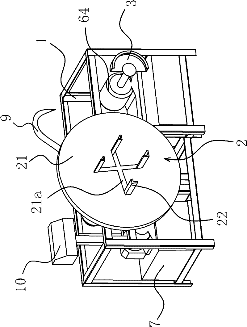
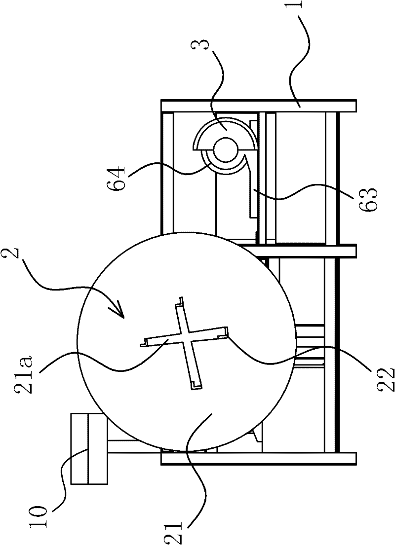
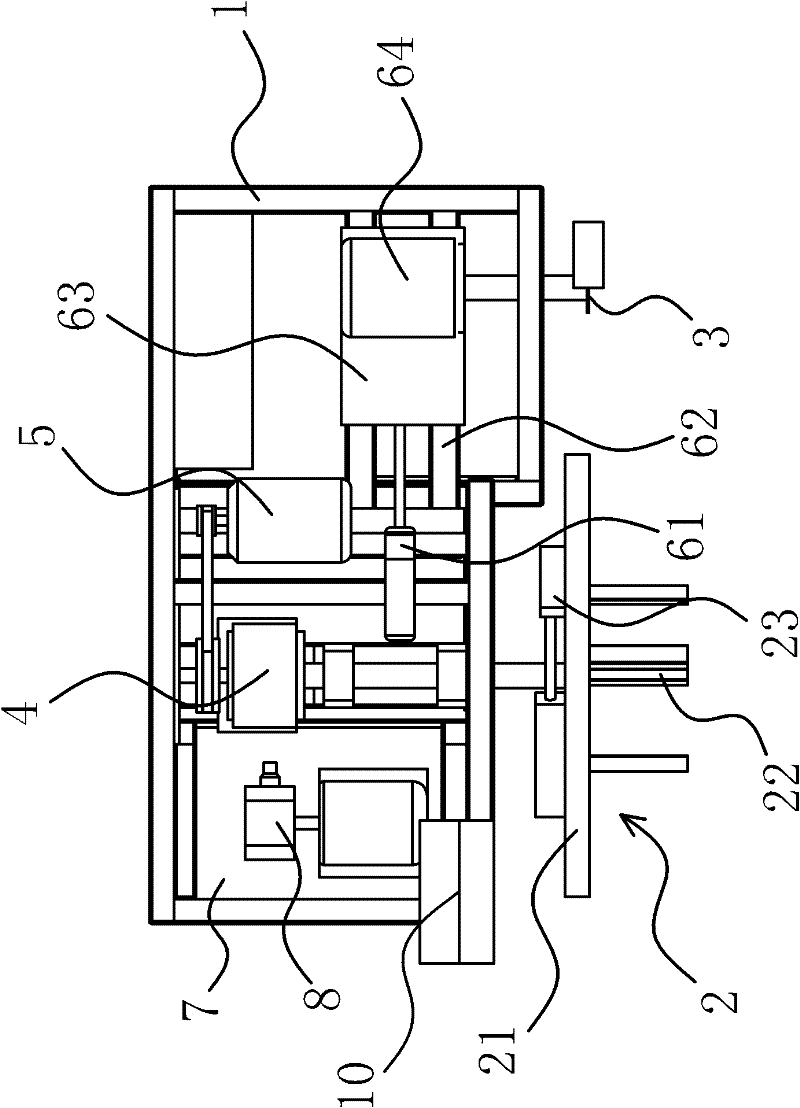
[0033] like figure 1 Shown tire automatic cutter, is made of frame 1, motor 5, motor two 64, cutter 3, clamp 2 etc. The frame 1 is welded by channel steel and triangle iron, the middle part of the frame 1 is provided with a motor 5, and the side close to the motor 5 is provided with a reducer 4, such as Figure 4 As shown, the reducer 4 is connected with the motor 5 through a belt, and the rotation of the motor 5 can drive the operation of the reducer 4 . The output end of speed reducer 4 is connected with a connecting shaft, and the outer end of this connecting shaft stretches out the side part of frame 1, and the clamp 2 for clamping waste tires is provided at the outer end of connecting shaft. The motor 5 rotates to d...


PUM


Abstract

The invention provides an automatic tyre cutting machine, belonging to the technical field of machinery. The automatic tyre cutting machine solves the problems that a traditional waste tyre cutting machine is inconvenient to operate and has high machining cost. The automatic tyre cutting machine comprises a frame, a fixture arranged at the side of the frame and used for lamping a tyre, and a cutter arranged corresponding to the fixture, wherein the fixture is connected with a speed reducer which can drive the cutter to rotate, the speed reducer is driven by a motor, a power assembly which can drive the cutter to be away from or close to the fixture is arranged on the frame, and the cutter is arranged on the power assembly. The automatic tyre cutting machine has the advantages of simpleness in operation, high safety, excellent stability, high work efficiency and the like.

Description

technical field [0001] The invention belongs to the technical field of machinery, and relates to a cutting machine, in particular to an automatic tire cutting machine. Background technique [0002] With the rapid development of the automobile industry, the management and treatment of waste tires is becoming more and more important, so the waste tire treatment industry has emerged as the times require. Now, the reuse of waste tires has become a reality, mainly for the production of rubber powder, reclaimed rubber, and pyrolysis. No matter what the purpose is, it is necessary to classify the waste tires, cut the rubber, and separate the different parts of the waste tires. Come, for the production of different varieties of products, in preparation for the next process. The current manufacturers generally use sickle and guillotine to cut the recycled waste tires. The disadvantage of this cutting method is: due to the thick rubber layer of the tire, manual cutting is quite labor...

Claims


Application Information

Patent Timeline
Patent Type & Authority Applications(China)
IPC IPC(8): B24B27/06
Inventor 王益明
Owner 王益明
Why Eureka
Try Eureka