
Novel long shaft placing device

A long shaft, a new type of technology, applied in the field of jigs for placing long shaft parts, can solve the problem of shaft wear at the end of the shaft, and achieve the effect of preventing wear or deformation

Inactive Publication Date: 2013-09-04
SUZHOU SUTENG ELECTRONICS TECH
View PDF5 Cites 0 Cited by
  • Summary
  • Abstract
  • Description
  • Claims
  • Application Information

AI Technical Summary

Problems solved by technology

[0003] (1) During normal storage, the end of the shaft or the shaft body is worn due to rolling or sliding;

Method used


Image

  • Novel long shaft placing device
  • Novel long shaft placing device

Examples


Embodiment Construction

[0016] The present invention will be described in further detail in combination below.

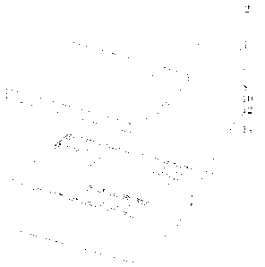
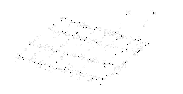
[0017] Such as figure 1 with figure 2 As shown, the present invention includes a box body 6, and the box body 6 includes a bottom plate 14, a side plate 12 fixed above the bottom plate 14 and forming a circle, and at least two rod-shaped supports 4 arranged on the bottom plate 14. 4. A concave support portion 8 is provided on the top. The characteristic is that the upper surface of the bottom plate 14 is provided with accommodating holes 16 that can accommodate the bottom of the support 4. There are at least three accommodating holes 16 distributed in a rectangular array on the bottom plate 14. .

[0018] Place the two ends of the major axis in the support portion 8 of the support member 4, because the support portion 8 is concave, and the contact surface between the support portion 8 and the end of the major axis is a curved surface with a large area, which can be Restrict the sliding...


PUM


Abstract

The invention discloses a novel long shaft placing device. The novel long shaft placing device comprises a box body (6). The box body (6) comprises a base plate (14), lateral plates (12) which are fixed above the base plate (14) and arranged in a circle, and at least two rod-shaped supports (4) arranged on the base plate (14), wherein a concave support portion (8) is arranged at the top of each support (4), containing holes (16) are arranged on the upper surface of the base plate (14), the bottoms of the supports (4) can be inserted into the containing holes (16), the number of the containing holes (16) is at least three, and the containing holes (16) are distributed on the base plate (14) in rectangular array mode. Two ends of a long shaft are placed in the support portions (8) of the supports (4), and sliding and rolling of the long shaft are restricted to a greater degree and the long shaft is prevented from being worn or deformed caused by the sliding and the rolling due to the fact that the support portions (8) are concave and contact surfaces of the support portions (8) and the ends of the long shaft are curved and large in area. In addition, the support portions (8) can be connected into the containing holes (16) in detachable mode, and the containing holes (16) are distributed in rectangular array mode, and accordingly a worker can choose two supports (4) and respectively clamp the two supports (4) into the containing holes (16) with a corresponding interval according to the length of the long shaft, and long shafts with different shaft lengths can be fitted.

Description

technical field [0001] The invention relates to the field of machining, in particular to a jig for placing long shaft parts. Background technique [0002] A long shaft workpiece is a shaft part with a relatively large ratio of length to diameter. This kind of part will at least encounter the following situations in the usual process of inclusion: [0003] (1) During normal storage, the end of the shaft or the shaft body is worn due to rolling or sliding; [0004] (2) During normal storage, the shaft body is deformed by radial force; [0005] In view of this, the present invention has been studied at the above-mentioned defect in the prior art, then has the generation of this case. Contents of the invention [0006] The technical problem to be solved by the present invention is to provide a device capable of reducing the wear of long-axis workpieces during placement. [0007] In order to solve the above problems, the present invention provides a novel long-axis placement...

Claims


Application Information

Patent Timeline
Patent Type & Authority Applications(China)
IPC IPC(8): B25H3/02
Inventor 周天毫
Owner SUZHOU SUTENG ELECTRONICS TECH
Learn More