Hydraulic automatic flushing system

An automatic flushing and hydraulic technology, applied in water supply devices, flushing equipment with water tanks, buildings, etc., can solve the problems of power consumption, false triggering, waste of water resources, etc., and achieve good social and economic effects

Inactive Publication Date: 2013-09-04
SHANGHAI JIAO TONG UNIV
View PDF6 Cites 4 Cited by
  • Summary
  • Abstract
  • Description
  • Claims
  • Application Information

AI Technical Summary

Problems solved by technology

Although this kind of device can solve the function of automatically flushing the toilet, it consumes electric energy, especially in occasions where there are few people such as holidays or late at night, it is always in the detection state and consumes electric energy continuously
Moreover, when someone passes by, there will be a false trigger state, and the toilet will be flushed by mistake, resulting in a waste of water resources
Therefore, infrared sensors have certain limitations in practical applications

Method used


Image

  • Hydraulic automatic flushing system

Examples


Embodiment Construction

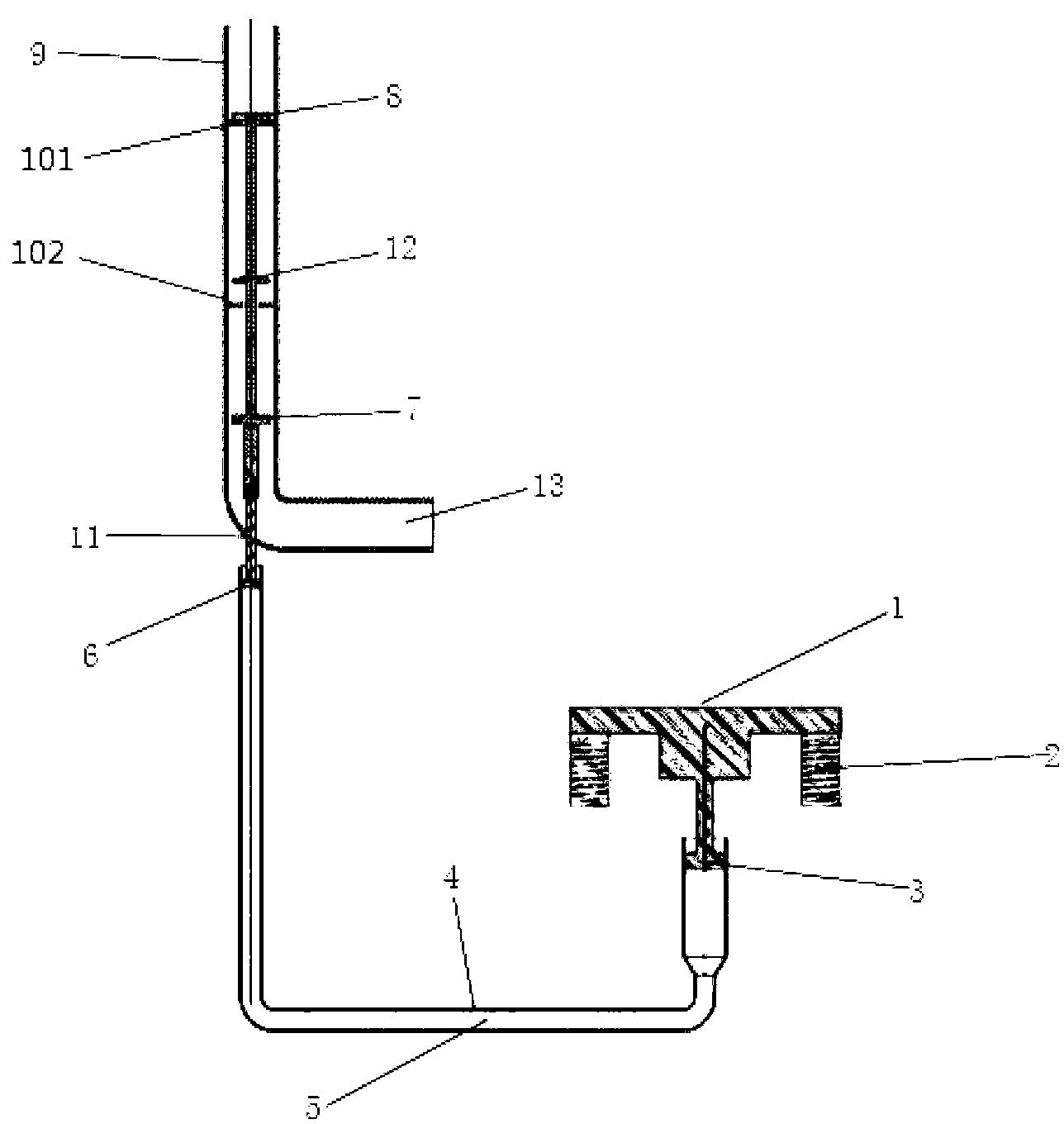
[0015] Such as figure 1 As shown, the present embodiment invention includes a pedal 1, a spring 2 arranged on the ground and installed on the lower surface of the pedal, a hydraulic cylinder and a water storage device. The water storage device includes a water pipe 9, and an upper throttle valve 8, an upper throttle plate 101, a drain piston 12, a lower throttle plate 102, and a lower throttle valve 7 arranged sequentially in the water pipe 9 along the flow direction. , wherein, the lower throttle valve 7, the drain piston 12 and the upper throttle valve 8 are rigidly connected through connecting rods, and can move up and down as a whole, and the upper throttle plate 101 and the lower throttle plate 102 are rigidly fixed in the water pipe 9 at intervals; The hydraulic cylinder includes a U-shaped tube connector 4, hydraulic oil 5 filled in the U-shaped tube connector, and a first hydraulic cylinder piston 3 installed on the pedal 1 side of the U-shaped tube connector 4 , and ...


PUM


Abstract

A hydraulic automatic flushing system comprises a pedal, a spring, a hydraulic oil cylinder and a water storage device; the water storage device comprises a water pipe, an upper throttle valve, an upper throttle piece, a drainage piston, a lower throttle piece and a lower throttle valve; the upper throttle valve and the upper throttle piece are sequentially arranged in the water pipe; the lower throttle piece, the water discharge piston and the upper throttle valve are connected in a rigidity mode through a connection rod; the upper throttle piece and the lower throttle piece are fixed inside the water pipe in an interval mode; the hydraulic oil cylinder comprises a U-shaped pipe communicating vessel, hydraulic oil which is filled in the U-shaped pipe communicating vessel, a first hydraulic cylinder piston and a second hydraulic cylinder piston; the first hydraulic cylinder piston and the second hydraulic cylinder piston are arranged on bilateral sides of the U-shaped pipe communicating vessel; the lower portion of the lower throttle valve is connected with the second hydraulic cylinder piston through the connection rod; and the lower surface center of the pedal is connected with the first hydraulic cylinder piston through the connection rod. The hydraulic automatic flushing system achieves water storage when being trod through a person and achieves the automatic flushing function of performing pressurization flushing when the person leaves.

Description

technical field [0001] The invention relates to an automatic toilet flushing device, in particular to a purely mechanically realized automatic flushing system without energy consumption, which belongs to the technical field of mechanical automation. Background technique [0002] With the improvement of living standards and changes in lifestyles, the automation of toilet flushing devices in public places is getting higher and higher. For example, the urinals in the male toilets in airports, shopping malls, hotels, guesthouses, schools, office buildings and other places generally need toilet flushing devices. In the more general toilets, the manual flushing device is more common, that is, pressing by hand or stepping on the toilet; in the toilets with higher grades, most of them are automatic flushing systems to maximize the user's safety. Convenience and civility. The biggest disadvantage of the manual flushing system is that people need to consciously press and flush. When...

Claims


Application Information

Patent Timeline
Patent Type & Authority Applications(China)
IPC IPC(8): E03D5/08
Inventor 姚晔王浩宇林杰张熹浩
Owner SHANGHAI JIAO TONG UNIV
Why Eureka
Try Eureka