Shale oil and gas field detection device

A technology for on-site detection and shale oil and gas, applied in the direction of measuring devices, material analysis through electromagnetic means, instruments, etc., can solve the problems of large errors and long time consumption, and achieve moderate volume, high feasibility, great social significance and practicality value effect

Pending Publication Date: 2020-08-28
中石化石油工程技术服务有限公司 +2
View PDF0 Cites 2 Cited by
  • Summary
  • Abstract
  • Description
  • Claims
  • Application Information

AI Technical Summary

Problems solved by technology

Among them, the desorption method is a direct method for measuring shale gas content, and it is also the most commonly used method. It can reflect the gas-bearing characteristics of shale under the conditions of simulating the actual formation environment, so it is used as the basic method for measuring shale gas content. method, but this method takes a long time and has large errors; isothermal adsorption method and logging interpretation method are indirect methods for shale gas content determination
Isothermal adsorption is the reverse process of desorption. Through isothermal adsorption simulation, the adsorption characteristics and capacity of organic-rich shale can be studied, and the parameter data of adsorbed gas content can be obtained. Inappropriate, and the error is large; the logging interpretation method is a method to obtain the gas content of shale through the interpretation of logging data. This method first needs to establish the rock-electricity relationship, including rock density and organic matter content, radioactive material content and organic matter content, The relationship between organic matter content and gas content, etc., and then interpret the adsorbed gas content, free gas content and total gas content through logging data. However, the rock-electricity relationship of shale gas in my country has not yet been effectively established.

Method used


Image

  • Shale oil and gas field detection device
  • Shale oil and gas field detection device
  • Shale oil and gas field detection device

Examples


Embodiment Construction

[0036] The following is one of the preferred embodiments of this patent:

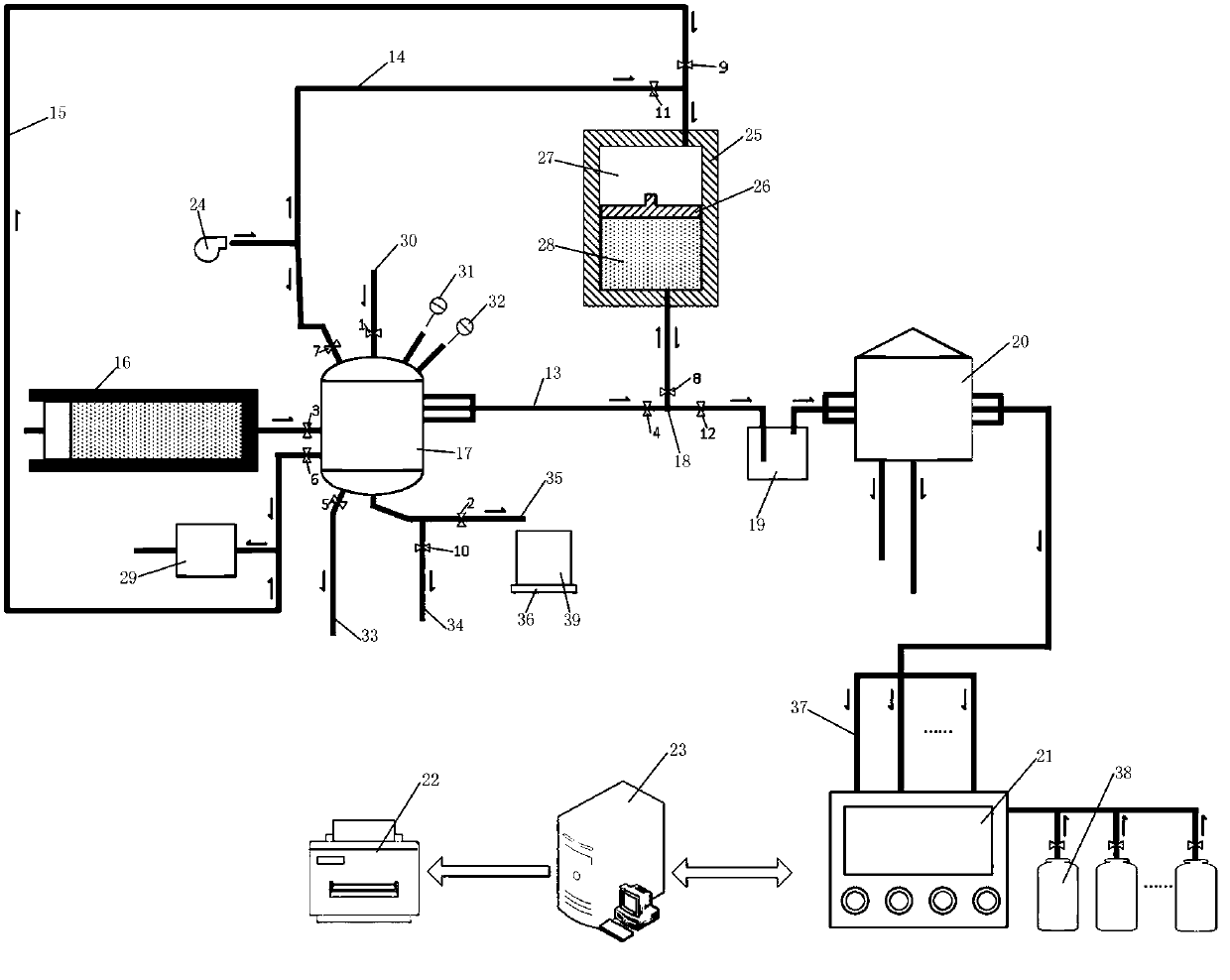
[0037] refer to figure 1 Shown is a shale oil and gas on-site detection device, which includes a gas collector 16, a vacuum pump 29, a blower 24, a pressure balance tank 17, a filter device 19, a cylinder pressurization device 25, a mass spectrometer 21, and an industrial control computer (hereinafter Referred to as the industrial computer 23), the pressure parameter is used as the main control parameter, and the pressure is gradually reduced.

[0038] The first pipeline 13, the first pipeline 13 communicates with the air collector 16, the third solenoid valve 3, the pressure balance tank 17, the fourth solenoid valve 4, the first three-way pipe 18, and the twelfth solenoid valve in sequence from left to right 12. Filtering device 19, pre-filtering device 20, mass spectrometer 21.

[0039]The second pipeline 14 communicates with the pressure balance tank 17, the seventh solenoid valve 7, the second th...


PUM


Abstract

Ashale oil and gas field detection device comprises a gas collecting cylinder, a pressure balancing tank, a filtering device, a front filtering device, a mass spectrum analyzer, an industrial personalcomputer and a printer, according to the device, the waiting time of shale oil and gas collection decision can be greatly shortened, the gas composition can be automatically detected, and a detectionresult is displayed through display equipment; the device has multiple expression modes, can be operated without professional knowledge (only opening and closing buttons need to be controlled), integrates an automatic flushing function and automatic flushing of equipment after detection, greatly improves the feasibility of field operation, has a proper volume, can be configured on a moving vehicle, and adapts to shale oil and gas component detection under various conditions; gas-liquid separation, liquid phase volume and mass measurement, gas total amount measurement, online measurement of gas components and concentration and automatic flushing of equipment can be realized, the volume is moderate, and the field operability is extremely high; the measurement can be realized aiming at the gas under the gas pressure in a larger range, and the social significance and the practical value are higher.

Description

technical field [0001] This patent relates to the field of on-site detection of shale oil and gas, specifically a device for on-site detection of shale oil and gas. Background technique [0002] Existing test methods for shale gas content include desorption method, isothermal adsorption method, logging interpretation method, etc. Among them, the desorption method is a direct method for measuring shale gas content, and it is also the most commonly used method. It can reflect the gas-bearing characteristics of shale under the conditions of simulating the actual formation environment, so it is used as the basic method for measuring shale gas content. method, but this method takes a long time and has large errors; isothermal adsorption method and logging interpretation method are indirect methods for determining shale gas content. Isothermal adsorption is the reverse process of desorption. Through isothermal adsorption simulation, the adsorption characteristics and capacity of ...

Claims


Application Information

Patent Timeline
Patent Type & Authority Applications(China)
IPC IPC(8): G01N27/62
CPCG01N27/62
Inventor 裴学良孙浩玉吴仲华刘丹陈忠帅马文武李风叶司英晖聂云飞庄伟赵传伟王彬刘畅张锐于波赵宗锋
Owner 中石化石油工程技术服务有限公司
Why Eureka
Try Eureka