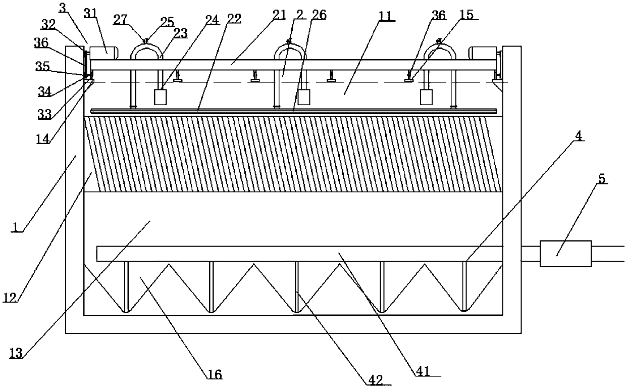
Reverse-flow sedimentation tank inclined pipe flushing system
A flushing system and sedimentation tank technology, which is applied in the direction of settling tanks, etc., can solve the problems of low cleaning efficiency, waste of resources, and inconvenient cleaning
- Summary
- Abstract
- Description
- Claims
- Application Information
AI Technical Summary
Problems solved by technology
Method used
Image
Examples
Embodiment 1
[0025] A reverse flow sedimentation tank inclined tube flushing system, comprising a sedimentation tank body 1, the sedimentation tank body 1 is sequentially provided with a mud sedimentation area 13, an inclined tube sedimentation area 12, and a water collection area 11 from bottom to top. A flushing device 2 is provided in the catchment area 11, and the flushing device 2 includes a support frame 21 whose length is the same as the width of the sedimentation tank body 1, and a cleaning main pipe 22 is arranged below the support frame 21, and a cleaning main pipe 22 is provided on the cleaning main pipe 22. A plurality of sets of inverted U-shaped flushing pipes 23 are provided along the length direction of the cleaning main pipe 22. One end of the U-shaped flushing pipes 23 is provided with a small submersible pump 24, and the middle section of the U-shaped flushing pipes 23 is provided with a valve for adjusting pressure. Manual ball valve 25, the other end of the U-shaped flu...
Embodiment 2
[0027] On the basis of Embodiment 1, the moving mechanism 3 includes variable frequency deceleration motors 31 arranged on both ends of the upper end surface of the support frame 21. The output shaft of the frequency conversion deceleration motor 31 is provided with a sprocket one 32, and the support frame 21 Drive wheels 33 are provided at both ends of the lower end surface of the water collecting area 11, and main slide rails 14 are arranged on the left and right side walls of the sedimentation tank body 1 above the water collection area 11 along the length direction of the sedimentation tank body 1. 33 can freely roll along the length direction of the main slide rail 14 on the main slide rail 14, and the center of the driving wheel 33 is provided with a rotating shaft 34, and the outer end of the rotating shaft 34 is fixedly connected with a sprocket two 35, and the sprocket one 32 Link by chain 36 between sprocket wheel two 35.
Embodiment 3
[0029] On the basis of Embodiment 1 or 2, a plurality of groups of driven wheels 37 are uniformly arranged under the middle section of the support frame 21, and the sedimentation tank body 1 above the water collection area 11 is along the length direction of the sedimentation tank body 1 Multiple groups of secondary slide rails 15 are provided, and the secondary slide rails 15 have the same length as the main slide rails 14 and are located on the same plane as the main slide rails 14. The driven wheels 37 correspond to the secondary slide rails 15 one by one and can The slide rail 15 freely rolls along the length direction of the secondary slide rail 15 .
PUM
 Abstract
Description
Claims
Application Information
 - R&D
- Intellectual Property
- Life Sciences
- Materials
- Tech Scout
- Unparalleled Data Quality
- Higher Quality Content
- 60% Fewer Hallucinations
Browse by: Latest US Patents, China's latest patents, Technical Efficacy Thesaurus, Application Domain, Technology Topic, Popular Technical Reports.
© 2025 PatSnap. All rights reserved.Legal|Privacy policy|Modern Slavery Act Transparency Statement|Sitemap|About US| Contact US: help@patsnap.com

