Device for adjusting fluid distribution in pipeline and method thereof

A pipeline, gas-liquid distribution technology, applied in the direction of fluid flow, mechanical equipment, etc., can solve the problems of unfavorable fluid transportation, large pressure drop, etc., and achieve the effect of good rectification effect, reduced loss, easy installation and disassembly

Active Publication Date: 2013-09-04
ZHEJIANG UNIV
View PDF7 Cites 21 Cited by
  • Summary
  • Abstract
  • Description
  • Claims
  • Application Information

AI Technical Summary

Problems solved by technology

Although the rectifier has a good rectification effect on gas, it also has a large pressure drop, which is not conducive to the transportation of fluid

Method used


Image

  • Device for adjusting fluid distribution in pipeline and method thereof
  • Device for adjusting fluid distribution in pipeline and method thereof
  • Device for adjusting fluid distribution in pipeline and method thereof

Examples


Embodiment 1

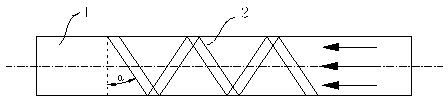
[0020] Such as figure 1 As shown, the spiral plate is installed in the horizontal pipeline to adjust the gas-liquid distribution in the pipeline. Among them, the diameter of the pipe is 882 mm and the length is 2000 mm; the starting point of the spiral plate is located at the lower part of the horizontal pipe where the liquid accumulates; the angle α between the line segment representing the spiral plate and the pipe diameter is 25°; the width W of the spiral plate is 50 mm , the angle θ between the surface where it is located and the tube wall surface is 45°; the spiral plate spirals forward counterclockwise relative to the fluid flow direction, and the number of rotations is 2.5. The experiment was carried out with air and water as the simulated medium, the gas flow rate was 12 m / s, and the mole fraction of water was 8%. When the spiral plate is not installed, the pressure drop between the inlet and outlet of the pipeline is 1060 Pa, and the variation coefficient of liquid ...

Embodiment 2

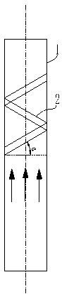
[0022] Such as figure 2 As shown in Fig. 1, a spiral plate is installed in a vertical pipeline to adjust the gas-liquid distribution in the pipeline. Among them, the diameter of the pipe is 882 mm, and the length is 2000 mm; the starting point of the spiral plate is located on the side of the pipe wall where the liquid accumulates; the angle α between the line segment representing the spiral plate and the pipe diameter is 30°; the width W of the spiral plate is 50 mm, the angle θ between the surface where it is located and the pipe wall surface is 60°; the spiral plate spirals forward clockwise relative to the direction of fluid flow, and the number of rotations is 1.5. The experiment was carried out with air and water as the simulated medium, the gas flow rate was 12 m / s, and the mole fraction of water was 8%. When the spiral plate is not installed, the pressure drop between the inlet and outlet of the pipeline is 1140 Pa, and the variation coefficient of liquid content on ...

Embodiment 3

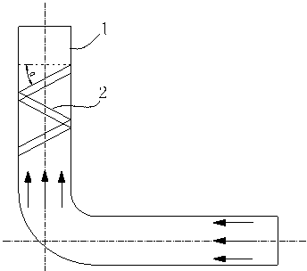
[0024] Such as image 3 As shown, a spiral plate is installed in the vertical pipeline behind the elbow to adjust the gas-liquid distribution in the pipeline. Among them, the diameter of the pipe is 882 mm, the length of the horizontal pipe is 1000 mm, the length of the vertical pipe is 2000 mm, and the elbow is a standard 90° elbow. The starting point of the spiral plate is located outside the vertical pipe where the liquid gathers downstream of the elbow; the angle α between the line segment of the spiral plate and the pipe diameter is 45°; the width W of the spiral plate is 45 mm, and the distance between the surface where it is located and the pipe wall surface The included angle θ is 30°; the spiral plate spirals forward clockwise relative to the fluid flow direction, and the number of rotations is 1.5. The experiment was carried out with air and water as the simulated medium, the gas flow rate was 14 m / s, and the mole fraction of water was 10%. When the spiral plate is...


PUM


Abstract

The invention discloses a device for adjusting fluid distribution in a pipeline and a method thereof. When gas-fluid mixed fluid flows through a spiral blocking plate, fluid on one side, where more fluid is distributed, of the pipe wall can move to one side where the fluid content is low in the rotation direction of the spiral blocking plate. Meanwhile, the spiral blocking plate can enable the flow speed of the gas-fluid mixed fluid to increase to improve mixing of gas and fluid. When the flow speed of mixed fluid is smaller than 20m/s, a spiral angle of the spiral blocking plate is larger than 45 degrees. When the flow speed of the mixed fluid is larger than 20m/s, the spiral angle of the spiral blocking plate is smaller than 45 degrees. The turn number n is equal to L/(tan alpha . D) - 2, the alpha is the spiral angle of the spiral blocking plate, and the D is the pipeline diameter. The device is excellent in rectification effect of fluid, suitable for rectifying various kinds of fluid, avoids blockage, prolongs service life of various assemblies and reactors after pipes are bent, is small in pressure drop, reduces conveying energy consumption, and meanwhile is simple in structure and easy to install and dismount.

Description

technical field [0001] The invention relates to a device for adjusting fluid distribution, in particular to a device and method for adjusting fluid distribution in a pipeline. Background technique [0002] In the chemical industry, elbows are often used to change the flow direction of the fluid to complete the delivery of the fluid. However, due to the centrifugal action of the bent pipe, the components of different densities in the mixed fluid will be separated, and the flow pattern of the fluid will change greatly, forming an unstable flow. When the fluid flows through the elbow, the inner side of the elbow has a higher speed and lower pressure, while the outer side has a lower speed and higher pressure. After entering the straight pipe section, the pressure on the inside of the bend gradually increases, and the pressure on the outside gradually decreases. After passing through the elbow, the fluid needs to pass through a long section of straight pipe to restore a stable...

Claims


Application Information

Patent Timeline
Patent Type & Authority Applications(China)
IPC IPC(8): F15D1/02
Inventor 黄正梁胡东芳王靖岱胡东辉孙婧元王宇良郑海俊冯翔郭健时强柳莺蒋斌波廖祖维阳永荣
Owner ZHEJIANG UNIV
Why Eureka
Try Eureka