
Synchronous rectification control circuit and power converter

A control circuit and synchronous rectification technology, applied in the direction of converting DC power input to DC power output, output power conversion device, adjusting electrical variables, etc. Short time, fast turn off and accurate effect

Pending Publication Date: 2021-02-23
SHENZHEN KIWI MICROELECTRONICS CO LTD
View PDF7 Cites 1 Cited by
  • Summary
  • Abstract
  • Description
  • Claims
  • Application Information

AI Technical Summary

Problems solved by technology

However, the turn-on and turn-off of the synchronous rectifier is regulated according to the control voltage of its gate, and the voltage jumps from one level to another with a certain delay, causing the turn-off delay of the synchronous rectifier, and The turn-off delay will lead to the commonality of the synchronous rectifier tube of the secondary circuit 102 and the switch Q of the primary side, which will cause reliability and stability problems of the system. reduced system efficiency

Method used


Image

  • Synchronous rectification control circuit and power converter
  • Synchronous rectification control circuit and power converter
  • Synchronous rectification control circuit and power converter

Examples


Embodiment Construction

[0034] Various embodiments of the invention will be described in more detail below with reference to the accompanying drawings. In the various drawings, the same elements are denoted by the same or similar reference numerals. For the sake of clarity, various parts in the drawings have not been drawn to scale.

[0035] The specific implementation manners of the present invention will be further described in detail below in conjunction with the accompanying drawings and embodiments.

[0036] "Connected" or "coupled" in the specification includes both direct connection and indirect connection. An indirect connection is a coupling through an intermediate medium, such as a coupling through an electrically conductive medium such as a conductor, where the electrically conductive medium may contain parasitic inductance or parasitic capacitance, or through the coupling of intermediate circuits or components described in the embodiments of the specification. Indirect connection can al...


PUM


Abstract

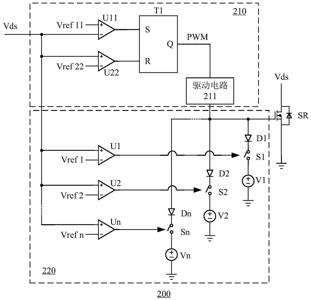
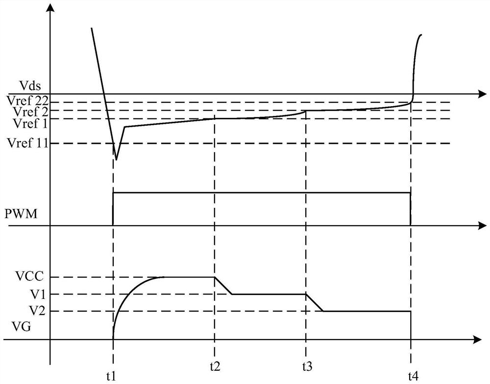
Disclosed are a synchronous rectification control circuit and a power converter. The power converter comprises the synchronous rectification control circuit, and the synchronous rectification controlcircuit comprises a main control circuit for controlling the on and off of a synchronous rectifier tube; and a voltage regulating circuit which is used for regulating the voltage output end to be connected to the control end of the synchronous rectifier tube and reducing the voltage at the control end of the synchronous rectifier tube before the synchronous rectifier tube is turned off within theturn-on time of the synchronous rectifier tube. According to the synchronous rectification control circuit and the power converter provided by the invention, the voltage variation when the synchronousrectification tube is turned off can be reduced, the turn-off delay of the synchronous rectification tube is reduced, and the reliability and stability of synchronous rectification control are improved.

Description

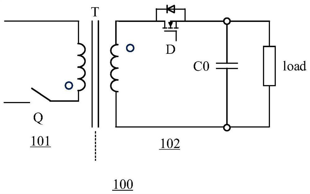
technical field [0001] The invention relates to the technical field of electronic circuits, in particular to a synchronous rectification control circuit and a power converter. Background technique [0002] power converters such as figure 1 The shown flyback voltage converter includes a primary circuit 101 and a secondary circuit 102 , and the primary circuit 101 and the secondary circuit 102 are isolated by a transformer T. The primary side switch Q of the primary side circuit 101 transmits energy to the secondary side circuit 102 through a switching action. The secondary side circuit 102 includes a rectifier device D. When the primary side switch Q is turned off, the rectifier device D is turned on, and the freewheeling current is used to supply power to the output capacitor C0 and the load load. When the freewheeling current drops to zero, the rectifier device D D is turned off, and at this time, the load is powered through the output capacitor C0. [0003] Among them, ...

Claims


Application Information

Patent Timeline
Patent Type & Authority Applications(China)
IPC IPC(8): H02M1/08H02M3/24H02M3/335H03K17/04
CPCH02M1/08H02M3/24H02M3/33592H03K17/04Y02B70/10
Inventor 文鹏曾强林官秋
Owner SHENZHEN KIWI MICROELECTRONICS CO LTD
Learn More