Rocket azimuth precise aiming system and rocket azimuth precise aiming method

A rocket and azimuth technology, applied in the field of rocket azimuth precision aiming system, can solve the problems of reduced work efficiency, low precision, long measurement time, etc., and achieve the effects of improving aiming and positioning accuracy, safety and power

Inactive Publication Date: 2015-04-22
CHANGCHUN INST OF OPTICS FINE MECHANICS & PHYSICS CHINESE ACAD OF SCI
View PDF6 Cites 0 Cited by
  • Summary
  • Abstract
  • Description
  • Claims
  • Application Information

AI Technical Summary

Problems solved by technology

[0005] When the visual aiming method is used for aiming measurement, it is necessary to repeatedly perform two-dimensional rail translation and visual aiming to make it aim at the target, resulting in long measurement time and cumbersome work steps
In addition, due to the extensive use of human eyes for aiming, the accuracy of rocket azimuth aiming is relatively low, about 10″ or more. This level of accuracy can no longer meet the current requirement that the satellite’s azimuth aiming accuracy should reach about 2″.
At the same time, in order to protect the safety of the user's eyes, the visual receiving system can only use extremely low-energy lasers, resulting in the need to repeat multiple times during the daytime aiming process to align, which greatly affects the preparation time for rocket launch. Reduced work efficiency

Method used


Image

  • Rocket azimuth precise aiming system and rocket azimuth precise aiming method
  • Rocket azimuth precise aiming system and rocket azimuth precise aiming method
  • Rocket azimuth precise aiming system and rocket azimuth precise aiming method

Examples


Embodiment Construction

[0023] The present invention will be further described in detail below in conjunction with the drawings.

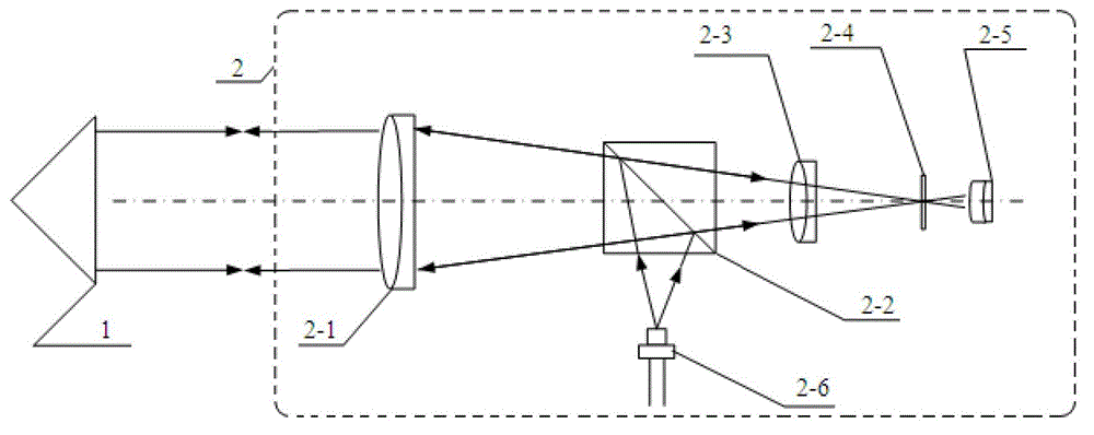
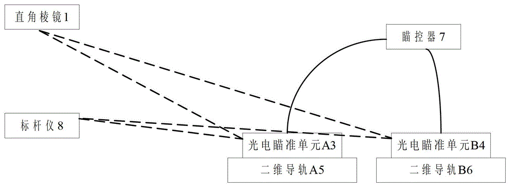
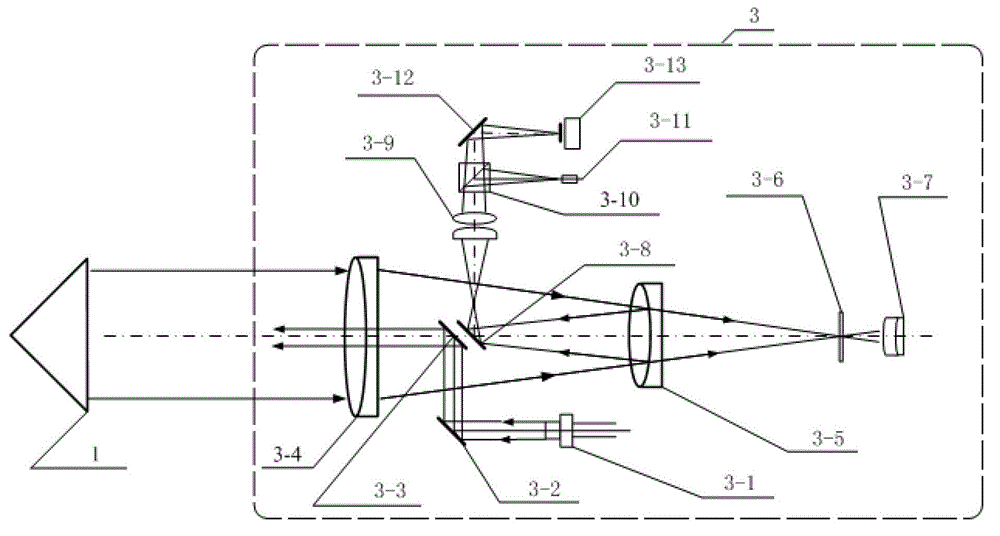
[0024] Such as figure 2 As shown, the rocket azimuth precision aiming system includes a right-angle prism 1, a photoelectric aiming unit A3, a photoelectric aiming unit B4, a two-dimensional guide rail A5, a two-dimensional guide rail B6, an aiming controller 7 and a benchmark 8. The two photoelectric aiming units have the same structure and are placed horizontally and coaxially, and the two two-dimensional guide rails have the same structure.

[0025] The right-angle prism 1 is installed horizontally on the rocket platform, marking the actual azimuth direction of the rocket. The benchmark 8 is placed at the fixed point of the benchmark after the geodetic survey, and the translational two-dimensional guide rail A5 and the two-dimensional guide B6 are respectively placed at the fixed point of the guide rail after the geodetic survey. The connecting direction of the benchmark ...


PUM


Abstract

The invention discloses a rocket azimuth precise aiming system and a rocket azimuth precise aiming method and belongs to the field of photoelectric aiming and measuring. The system comprises a right-angle lens, a benchmarking instrument, photoelectric aiming units, two-dimensional guide rails and an aiming controller. The method includes: the two photoelectric aiming units are mounted on the two two-dimensional guide rails, the two two-dimensional guide rails and the benchmarking instrument are mounted at three points of a calibrated straight line, and the direction of the straight line indicates the final positioning direction; an azimuth angle and a pitch angle of the photoelectric aiming unit B are adjusted to allow the aiming unit to aim at a benchmarking center of the benchmarking instrument; an azimuth angle and a pitch angle of the photoelectric aiming unit A are adjusted to allow the aiming unit to aim at a benchmarking center of the benchmarking instrument; the azimuth direction of each of the two photoelectric aiming units is kept, each of the two photoelectric aiming units is allowed to aim at the right-angle lens by adjusting the corresponding pitch angle, and the azimuth of each of the two-dimensional guide rails is adjusted to allow emitted laser of the corresponding photoelectric aiming unit to aim at the center of the right-angle lens; and data is measured in real time and transmitted to the aiming controller, and the azimuth of the right-angle lens is adjusted according to the azimuth angle value output and displayed by the aiming controller.

Description

Technical field [0001] The invention relates to a rocket azimuth precision aiming system and method, which are used for initial aiming when a carrier rocket is launched. The invention belongs to the field of photoelectric aiming measurement. Background technique [0002] Before the launch of the launch vehicle, the azimuth of the rocket needs to be adjusted to accurately align it with the direction to be launched. This requires a sophisticated real-time measurement system to complete the azimuth positioning adjustment through real-time measurement of the azimuth angle. [0003] In the existing aiming and measuring systems, the visual aiming method is mostly used. The system includes a right-angle prism, a benchmark, two visual aiming units and two two-dimensional guide rails. The right-angle prism is installed horizontally on the rocket platform, the benchmark is placed at the fixed point of the benchmark after the geodetic survey, the two two-dimensional guide rails are respectiv...

Claims


Application Information

Patent Timeline
Patent Type & Authority Patents(China)
IPC IPC(8): F41G1/01
Inventor 刘绍锦王志乾李建荣何锋赟于帅北沈铖武耿天文刘畅李冬宁蔡盛
Owner CHANGCHUN INST OF OPTICS FINE MECHANICS & PHYSICS CHINESE ACAD OF SCI
Why Eureka
Try Eureka