An optical fiber 1/4 wave plate phase delay temperature characteristic measuring device and method

A wave plate phase and measurement method technology, which is applied in the direction of testing optical performance, etc., can solve the problems of no optical fiber 1/4 wave plate phase delay temperature characteristic measurement method, affecting the measurement accuracy of optical fiber current transformers, and the inability to establish error models, etc. Achieve the effects of eliminating optical power fluctuations, ensuring detection sensitivity, and accurate online compensation

Active Publication Date: 2015-12-23
开元锐德(北京)光电科技有限公司
View PDF2 Cites 2 Cited by
  • Summary
  • Abstract
  • Description
  • Claims
  • Application Information

AI Technical Summary

Problems solved by technology

However, at present, since the establishment of the temperature characteristic model of the phase error of the 1 / 4 wave plate is based on theoretical derivation, there is no feasible method for measuring the temperature characteristic of the phase delay of the optical fiber 1 / 4 wave plate, and it is impossible to establish a more accurate error model, which affects the fiber current. Measurement accuracy of transformer

Method used


Image

  • An optical fiber 1/4 wave plate phase delay temperature characteristic measuring device and method
  • An optical fiber 1/4 wave plate phase delay temperature characteristic measuring device and method
  • An optical fiber 1/4 wave plate phase delay temperature characteristic measuring device and method

Examples


Embodiment Construction

[0015] The present invention will be further described in detail below in conjunction with the accompanying drawings and embodiments.

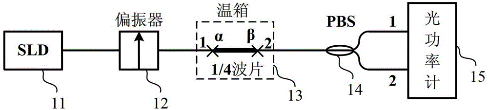
[0016] like figure 1 As shown, the optical fiber quarter wave plate phase retardation temperature characteristic measurement device provided by the present invention includes a broad-spectrum light source 11 , a polarizer 12 , a quarter wave plate 13 and a polarization beam splitter (PBS) 14 . figure 1 In the shown embodiment, the broad-spectrum light source 11 selects SLD. The light emitted by SLD11 is polarized into linearly polarized light by polarizer 12, and one end of the tested 1 / 4 wave plate 13 is fused with the output pigtail of polarizer 12 at an angle α on the axis, so the linearly polarized light generated by polarizer 12 is at 1 The / 4 wavelength plate 13 is decomposed into two orthogonal linearly polarized lights, and the two orthogonal linearly polarized lights are transmitted along the fast axis and the slow axis of the 1 / 4 wa...


PUM


Abstract

The invention discloses a device and a method for measuring a phase delay temperature characteristic of an optical fiber quarter wave plate, and belongs to the technical field of optical fiber current transformers. The device comprises a broad spectrum optical source, a polarizer, a quarter wave plate and a polarization beam splitter, wherein one end of the quarter wave plate is in direct-axis welding connection with output tail fibers of the polarizer at an angle alpha in a welding way, and the other end of the quarter wave plate is in direct-axis welding connection with input tail fibers of the polarization beam splitter at an angle beta. According to the method, light emitted from the broad spectrum optical source is polarized into linearly polarized light through the polarizer, the linearly polarized light is split into two beams of orthogonal linearly polarized light through the quarter wave plate, each of the two beams of linearly polarized light is split into two orthogonal linearly polarized light at the input tail fibers of the polarization beam splitter, two beams of linearly polarized light are interfered at a fast axis, two beams of linearly polarized light are interfered at a slow axis, and the phase delay of the quarter wave plate is solved by measuring the interference light intensity of the two output tail fibers of the polarization beam splitter. According to the device and the method, a more accurate phase delay temperature characteristic model for the optical fiber quarter wave plate can be established according to experimental data, and the test accuracy of an optical fiber current transformer can be improved.

Description

technical field [0001] The invention belongs to the technical field of optical fiber current transformers, and in particular relates to an optical fiber quarter wave plate phase delay temperature characteristic measuring device and method. Background technique [0002] Compared with traditional electromagnetic induction current transformers, all-fiber current transformers have the advantages of good insulation performance, light weight, no danger of magnetic saturation, large measurement range, and wide response frequency. greater development. At present, the main reason that restricts the practical use of fiber optic current transformers is that the current ratio accuracy is not high enough in the full temperature range (-40 ~ 60 ℃), and the long-term operation stability of the system needs to be improved. And the temperature stability of the phase difference error of the λ / 4 fiber wave plate is one of the most important factors affecting the accuracy of the current ratio ...

Claims


Application Information

Patent Timeline
Patent Type & Authority Patents(China)
IPC IPC(8): G01M11/02
Inventor 王夏霄王野李传生李立京于佳邬战军杨德伟王熙辰
Owner 开元锐德(北京)光电科技有限公司
Why Eureka
Try Eureka