Additional fault distance impact resistant line single-phase earthing fault single-end ranging method

A technology with additional fault distance and single-phase-to-ground fault, applied in the fault location and other directions, which can solve the problems of fault location failure, high application cost, and high sampling rate requirements.

Active Publication Date: 2013-09-04
STATE GRID CORP OF CHINA +2
View PDF4 Cites 2 Cited by
  • Summary
  • Abstract
  • Description
  • Claims
  • Application Information

AI Technical Summary

Problems solved by technology

The traveling wave method utilizes the transmission properties of fault transient traveling waves to perform single-ended fault location. It has high precision and is not affected by the operation mode and excessive resistance. However, it requires a high sampling rate, requires a special wave recording device, and has high application costs.
The impedance method uses the voltage and current after the fault to calculate the fault loop impedance, and performs single-ended fault distance measurement according to the characteristic that the line length is proportional to the impedance. It is simple and reliable, but the distance measurement accuracy is seriously affected by factors such as transition resistance and load current, especially When the transition resistance is large, due to the influence of the additional fault distance caused by the transition resistance, the measurement result of the fault distance will seriously deviate from the real fault distance, and even the fault distance measurement failure will occur.

Method used


Image

  • Additional fault distance impact resistant line single-phase earthing fault single-end ranging method
  • Additional fault distance impact resistant line single-phase earthing fault single-end ranging method
  • Additional fault distance impact resistant line single-phase earthing fault single-end ranging method

Examples


Embodiment Construction

[0015] The technical solution of the present invention will be further described in detail according to the accompanying drawings.

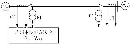
[0016] figure 1 It is a schematic diagram of the line transmission system applying the present invention. figure 1 Among them, PT is a voltage transformer, and CT is a current transformer. The protection device samples the voltage waveform of the voltage transformer PT and the current waveform of the current transformer CT at the transmission line protection installation to obtain the instantaneous value of voltage and current, and uses the Fourier algorithm to calculate the fault phase voltage at the transmission line protection installation Fault phase negative sequence current fault phase current and zero sequence current As an input; among them, φ=A phase, B phase, C phase.

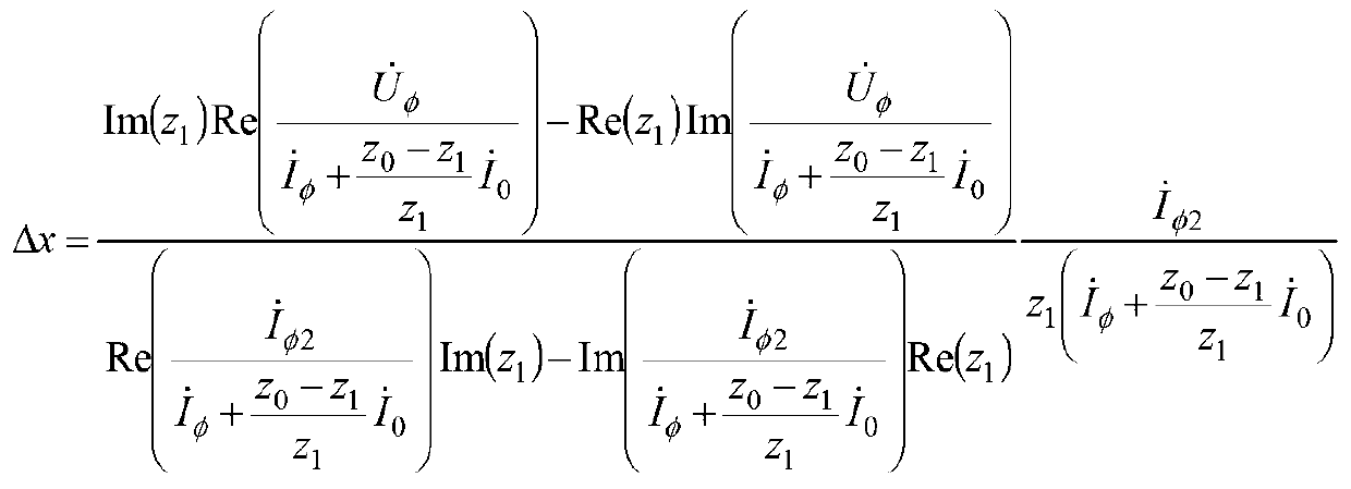
[0017] The protection device uses the transmission line to protect the fault phase voltage at the installation Fault phase negative sequence current fault p...


PUM


Abstract

The invention discloses an additional fault distance impact resistant line single-phase earthing fault single-end ranging method, which comprises the following steps of firstly, measuring fault phase voltage, fault phase negative sequence current, fault phase current and zero sequence current at a protection mounting part of a transmission line to be used as an input quantity; utilizing fault phase electrical quantity to calculate an additional fault distance caused by a transition resistance, and subtracting the additional fault distance caused by the transition resistance from the ratio of fault phase voltage to transmission line voltage drop per unit length to obtain the fault distance between the transmission line protection mounting part and a single-phase earthing fault point. The method provided by the invention overcomes the impact defects of the transition resistance and load current on single-end fault ranging precision, the ranging precision is high when the transmission line has a single-phase high resistance earthing fault, the ranging principle is simple, the program is easily realized, the fault distance is directly calculated without using a search algorithm, the ranging speed is quick, and the real-timeness is strong.

Description

technical field [0001] The invention relates to the technical field of electric power system relay protection, in particular to a single-terminal single-terminal ranging method for line single-phase grounding faults that is resistant to the influence of additional fault distances. Background technique [0002] The single-ended fault location method only uses the electrical quantity at one end of the transmission line for fault location, does not require communication and data synchronization equipment, has low operating costs and stable algorithms, and has been widely used in transmission lines. Single-ended ranging methods are mainly divided into traveling wave method and impedance method. The traveling wave method utilizes the transmission properties of fault transient traveling waves to perform single-ended fault location. It has high precision and is not affected by the operation mode and excessive resistance. However, it requires a high sampling rate, requires a special...

Claims


Application Information

Patent Timeline
Patent Type & Authority Applications(China)
IPC IPC(8): G01R31/08
Inventor 林富洪
Owner STATE GRID CORP OF CHINA
Why Eureka
Try Eureka