Gas-injection thrombosis-removal device and application thereof
A technology of air injection holes and air injection channels, applied in the field of medical devices, can solve the problems of increased bleeding risk and hemorrhage of patients, and achieve the effect of large thrombolytic effect, reduction of side effects and uniform force.
- Summary
- Abstract
- Description
- Claims
- Application Information
AI Technical Summary
Problems solved by technology
Method used
Image

Examples
Embodiment 1
[0023] Below in conjunction with the accompanying drawings, the air jet embolism removal device of the present invention will be further described.
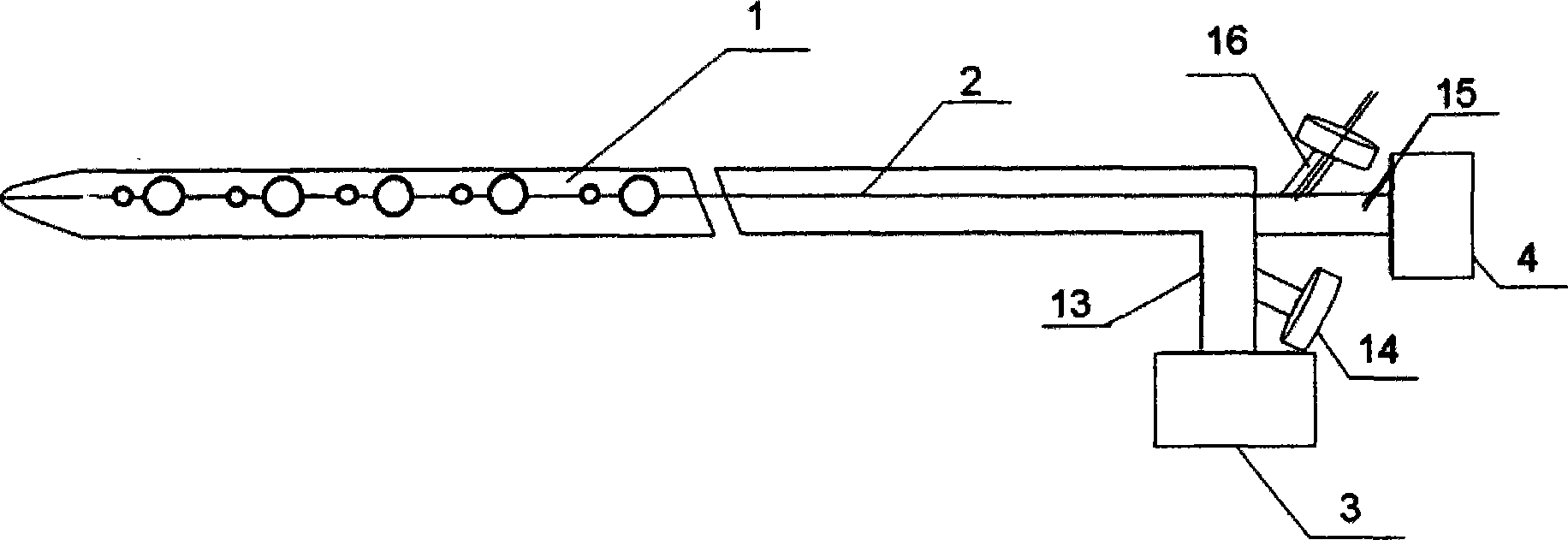
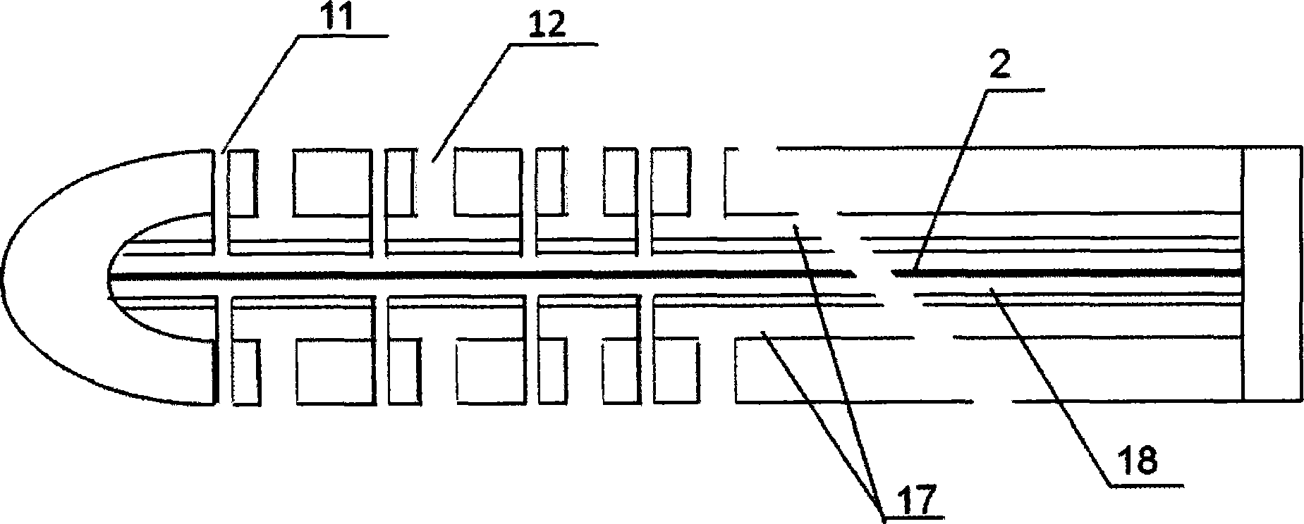
[0024] The air jet thrombus removal device of the present invention comprises: thrombolysis catheter 1, guide wire 2, suction pump 3 and gas pump 4, wherein thrombolysis catheter comprises two passages, and the outer passage is suction passage 17, and its diameter is 8F, and inner The channel is an air jet channel 18 whose diameter is 4F, the suction channel 17 and the air jet channel 18 are coaxial, and there is a guide wire 2 in the air jet channel. The total length of the thrombolytic catheter is 120 cm, and the effective part for removing thrombus is at the front of the thrombolytic catheter. In the range of 0.5-10 cm in front of the thrombolytic catheter, there are jet holes 11 with a diameter of 0.5 mm. On both sides of the duct, the number of jet holes on each side is 5. Suction holes 12 with a diameter of 1.5 mm are dist...
Embodiment 2
[0028]The air jet thrombus removal device of the present invention comprises: thrombolysis catheter 1, guide wire 2, suction pump 3 and gas pump 4, wherein thrombolysis catheter comprises two passages, and the outer passage is suction passage 17, and its diameter is 8F, and inner The channel is an air jet channel 18 whose diameter is 5F, the suction channel 17 and the air jet channel 18 are coaxial, and there is a guide wire 2 in the air jet channel. The total length of the thrombolytic catheter is 120 cm, and the effective part for removing thrombus is at the front of the thrombolytic catheter. In the range of 0.5-10 cm in front of the thrombolytic catheter, there are jet holes 11 with a diameter of 0.6 mm. On both sides of the duct, the number of jet holes on each side is 5. Suction holes 12 with a diameter of 1.6 mm are distributed in the range of 0.5-10 cm in front of the thrombolysis catheter. The suction holes 12 are distributed on both sides of the thrombolysis catheter...
Embodiment 3
[0030] The air jet thrombus removal device of the present invention comprises: thrombolysis catheter 1, guide wire 2, suction pump 3 and gas pump 4, wherein thrombolysis catheter comprises two passages, and the outer passage is suction passage 17, and its diameter is 8F, and inner The channel is an air jet channel 18 whose diameter is 5F, the suction channel 17 and the air jet channel 18 are coaxial, and there is a guide wire 2 in the air jet channel. The total length of the thrombolytic catheter is 120 cm, and the effective part for removing thrombus is at the front of the thrombolytic catheter. In the range of 0.5-10 cm in front of the thrombolytic catheter, there are jet holes 11 with a diameter of 0.6 mm. On both sides of the conduit, the number of air jet holes on each side is 8. Suction holes 12 with a diameter of 1.6 mm are evenly distributed within the range of 0.5 to 10 cm in front of the thrombolysis catheter. The suction holes 12 are distributed on both sides of the...
PUM
 Abstract
Description
Claims
Application Information
 - R&D Engineer
- R&D Manager
- IP Professional
- Industry Leading Data Capabilities
- Powerful AI technology
- Patent DNA Extraction
Browse by: Latest US Patents, China's latest patents, Technical Efficacy Thesaurus, Application Domain, Technology Topic.
© 2024 PatSnap. All rights reserved.Legal|Privacy policy|Modern Slavery Act Transparency Statement|Sitemap