Digital fitness chair

A fitness chair and digital technology, applied in the field of fitness equipment, can solve the problems of inability to adjust the height of the adjustable pedal, complex connection structure, poor use effect, etc., and achieve the effect of small space occupation, small volume and simple structure

Inactive Publication Date: 2013-09-11
于明强
View PDF6 Cites 2 Cited by
  • Summary
  • Abstract
  • Description
  • Claims
  • Application Information

AI Technical Summary

Problems solved by technology

Now there is a digital fitness chair, which can exercise both hands and feet through the handle mechanism and pedal mechanism arranged on it. The handle mechanism can exercise the hands by pushing and pulling the handle. The exercise of both feet can be achieved by stepping on, and both the handle mechanism and the pedal mechanism can realize digital output through the potentiometer to record the amount of exercise. The handle mechanism of the digital fitness chair has been named by the patent number 201020152981. "Universal box" discloses that the connecting rod connected with the handle in the handle mechanism realizes the universal swing of the handle through the transverse connecting piece and the longitudinal connecting piece respectively, and the transverse connecting piece and the longitudinal connecting piece are installed in the box body, This makes the rotating mechanism use more parts, the structure is more complicated, and it takes up a lot of space. Moreover, since the horizontal connector and the longitudinal connector are installed in the box body, the connecting rod needs to pass through the box body. When the connecting rod After swinging at a certain angle, the connecting rod will be blocked by th...

Method used


Image

  • Digital fitness chair
  • Digital fitness chair
  • Digital fitness chair

Examples


Embodiment Construction

[0026] The present invention will be described in further detail below with reference to the accompanying drawings and specific embodiments.

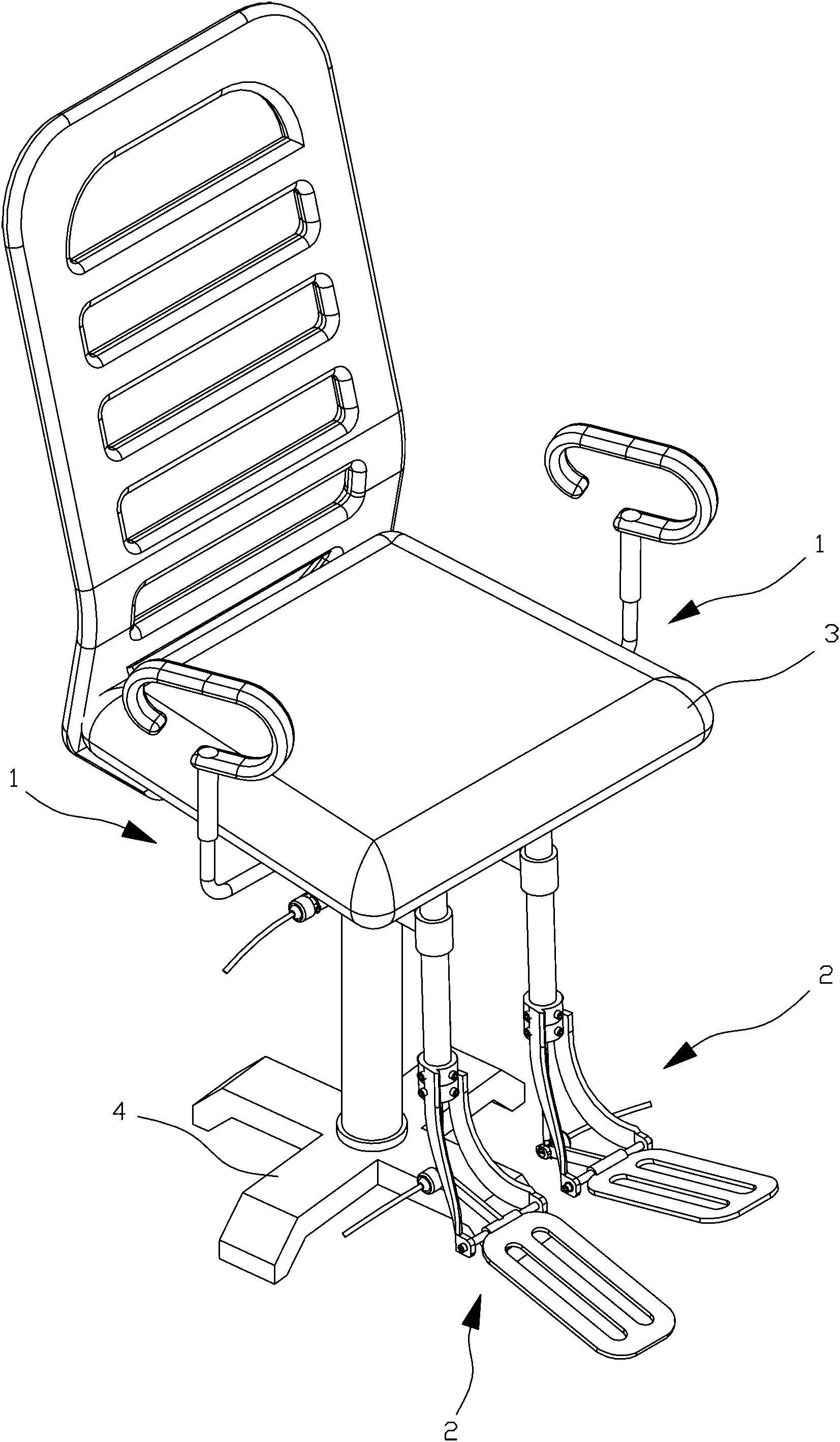
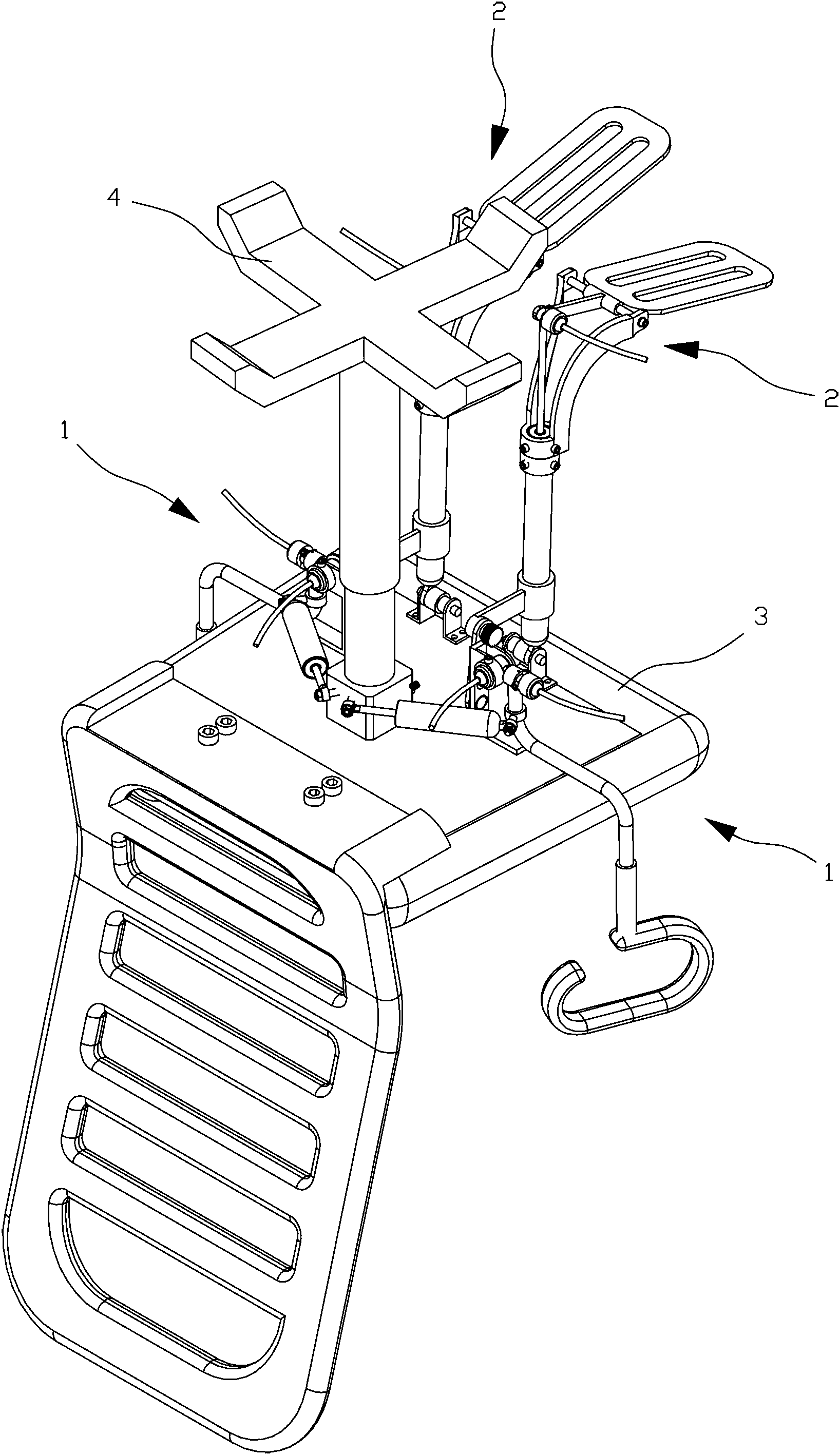
[0027] Depend on figure 1 , figure 2 As shown in the figure, the digital fitness chair of the present invention includes a seat body 3 with a support frame 4 below, a handle mechanism 1 is provided on each side of the seat body 3, and two footrests are provided on the front lower side of the seat body 3 Institution 2.

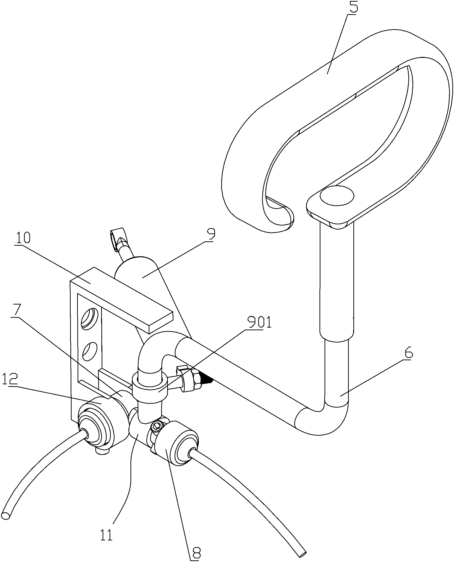
[0028] Depend on image 3 , Figure 4As shown, the two handle mechanisms 1 include a handle 5, a first connecting rod 6, a first potentiometer 8, a second potentiometer 12 and a first damping device 9. One end of the first connecting rod 6 is connected to the handle 5 The two handle mechanisms 1 also include a mounting seat 7 and a bracket 10. The first connecting rod 6 is N-shaped, that is to say, the first connecting rod 6 includes a horizontally arranged crossbar, one end of the crossbar is There is a vertical r...


PUM


Abstract

The invention discloses a digital fitness chair. Handle mechanisms are arranged on the two sides of a chair body respectively, two pedal mechanisms are arranged on the front lower side of the chair body, first connecting rods in the handle mechanisms are in the shape of N, one ends of the first connecting rods are connected with handles, mounting sleeves are arranged at the other ends of the first connecting rods, the mounting sleeves are movably sleeved and combined on mounting seats, first potentiometers are arranged at one ends of the mounting seats, the rotating shafts of the first potentiometers and the mounting sleeves are circumferentially limited, the other ends of the mounting seats are hinged to supports, second potentiometers are arranged on the supports, the rotating shafts of the second potentiometers are arranged in the hinge holes of the other ends of the mounting seats, the rotating shafts of the second potentiometers and the mounting seats are circumferentially limited, and supporting rods in each pedal mechanism are composed of a first supporting rod and a second supporting rod, one ends of the first supporting rods and one ends of the second supporting rods are hinged and can be locked, and the other ends of the first supporting rod and the other ends of the second supporting rods are fixed with a cylinder barrel and the bottom portion of the chair body respectively. The digital fitness chair is simple in structure, the rotating angle of the handles is large, and the height of pedals can be adjusted.

Description

technical field [0001] The invention relates to a fitness equipment, in particular to a digital fitness chair. Background technique [0002] With the improvement of living standards, people pay more and more attention to health, and more and more people use fitness equipment for fitness. Now there is a digital fitness chair, which can exercise both hands and feet through the handle mechanism and the pedal mechanism arranged on it. The handle mechanism realizes the exercise of the hands by pushing and pulling the handle, and the pedal mechanism Stepping is performed to exercise the feet, and both the handle mechanism and the pedal mechanism can realize digital output through the potentiometer to record the amount of exercise. "Universal Box" discloses that the connecting rod connected to the handle in the handle mechanism realizes the universal swing of the handle through a transverse connecting piece and a longitudinal connecting piece respectively, and the transverse conne...

Claims


Application Information

Patent Timeline
IPC IPC(8): A63B22/04A63B21/015A63B21/00A63B23/12A63B71/06
Inventor 陆昱森
Owner 于明强
Why Eureka
Try Eureka