Combined double keel decorative board

A combined and decorative panel technology, applied in the direction of floors, buildings, building structures, etc., can solve the problems of wood panel arching deformation, large shrinkage gaps, large transverse stress, etc., and achieve the effect of preventing arching deformation

Active Publication Date: 2017-03-29
李新发
View PDF10 Cites 0 Cited by
  • Summary
  • Abstract
  • Description
  • Claims
  • Application Information

AI Technical Summary

Problems solved by technology

[0004] like figure 1 As shown, there is currently a floor on the market, its two adjacent wooden boards A1 are connected together through the yin and yang groove A13 and the keel A2, the keel A2 has the main reinforcement A21 and the auxiliary reinforcement A22, the main reinforcement A21 and the auxiliary reinforcement A22 are inserted into the In the matching main rib slot A11 and auxiliary rib slot A12 on the wooden board A1, its disadvantages are: 1. When the wooden board is wet and swollen, a large transverse stress will be generated between two adjacent wooden boards , this stress can easily lead to arching and deformation of wood panels
2. When the wood boards are cold-shrinked, it is easy to see a large shrinkage gap between two adjacent wood boards on the surface of the wood boards

Method used


Image

  • Combined double keel decorative board
  • Combined double keel decorative board
  • Combined double keel decorative board

Examples


Embodiment 2

[0029] Example 2, see Figure 5 As shown, the positions of the right auxiliary rib 14 and the right auxiliary rib groove tenon 22 of the upper keel are exchanged. All the other are with embodiment 1.

Embodiment 3

[0030] Example 3, see Image 6 , 7 As shown, the hollow fitting part 21 extends laterally with the groove tenon 23 of the right auxiliary reinforcement of the second upper keel, and the groove tenon 23 of the right auxiliary reinforcement of the second upper keel is inserted into the matching slot on the wooden board 3 . All the other are with embodiment 2. Image 6 with Figure 7 The difference is that the position of the second upper keel right auxiliary rib groove tenon 23 is different.

Embodiment 4

[0031] Example 4, see Figure 8 As shown, the fitting portion 21 is formed with an oblique tenon 24 whose upper surface is inclined, and the oblique tenon 24 is inserted into the matching oblique groove 34 on the wooden board 3 . All the other are with embodiment 1.

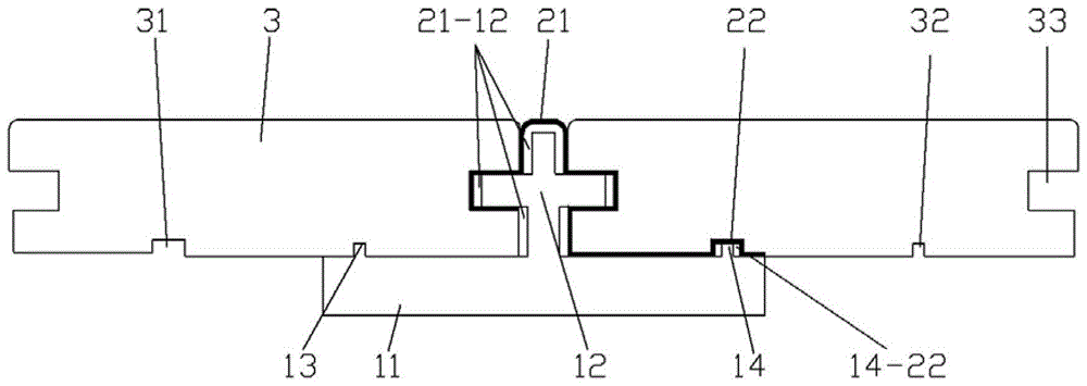
[0032] Working principle: When the two adjacent wooden boards 3 swell, the transverse stress between the two adjacent wooden boards 3 is effectively eliminated due to the elasticity of the upper keel 2, so that the wooden boards will not cause arching deformation , There is a transverse gap 21-12 between the hollow fitting part 21 and the main rib 12 which is not less than 1mm. The transverse gap 21-12 of the main reinforcement and the lateral gap 14-22 of the auxiliary reinforcement are to give space for deformation of the wooden board 3 and the upper keel 2 .

[0033] When the wooden board shrinks, the elastic upper keel 2 will return to its original shape, thus ensuring that the shrinkage gap seen on the sur...


PUM


Abstract

Combined double keel decorative panel, the right auxiliary rib, the left auxiliary rib and the right auxiliary rib are respectively located on the two sides of the main rib; the upper part of the upper keel is a hollow fitting part, and the hollow fitting part extends horizontally with a groove for the right auxiliary rib of the upper keel Tenon, the right auxiliary rib is placed in the groove of the right auxiliary rib of the upper keel, the right auxiliary rib of the upper keel is inserted into the matching right auxiliary rib groove on the wooden board, and the left auxiliary rib is inserted into the matched wooden board In the slot of the left auxiliary rib, the hollow fitting part fits on the main rib, and the hollow fitting part fits into the matching main rib slot on the wooden board; between the right auxiliary rib and the groove tenon of the right auxiliary rib of the upper keel There is a lateral gap of not less than 1mm in the auxiliary reinforcement, and there is a lateral gap of not less than 1mm in the main reinforcement between the hollow fitting part and the main reinforcement. It can effectively prevent the arching and deformation of the wooden board, and ensure that the shrinkage gap seen on the surface of the wooden board is small.

Description

[0001] Technical field: [0002] The invention relates to the technical field of decorative panels, in particular to a combined double keel decorative panel. [0003] Background technique: [0004] Such as figure 1 As shown, there is currently a floor on the market, its two adjacent wooden boards A1 are connected together through the yin and yang groove A13 and the keel A2, the keel A2 has the main reinforcement A21 and the auxiliary reinforcement A22, the main reinforcement A21 and the auxiliary reinforcement A22 are inserted into the In the matching main rib slot A11 and auxiliary rib slot A12 on the wooden board A1, its disadvantages are: 1. When the wooden board is wet and swollen, a large transverse stress will be generated between two adjacent wooden boards , this stress is likely to cause arching and deformation of the wooden board. 2. When the wood boards are cold-shrinked, it is easy to see a large shrinkage gap between two adjacent wood boards on the surface of the ...

Claims


Application Information

Patent Timeline
Patent Type & Authority Patents(China)
IPC IPC(8): E04F15/04
Inventor 李新发
Owner 李新发
Why Eureka
Try Eureka